F5 Distributed Cloud - Customer Edge Source | Edit on
Class 2: [Day-0] CE - Infrastructure Provisioning
Objective
Onbord and deploy CE on-prem / data center
Note
Onboarding steps/process of CE in UDF(KVM-based) similar to onboarding on VMWare ESXi hypervisor.
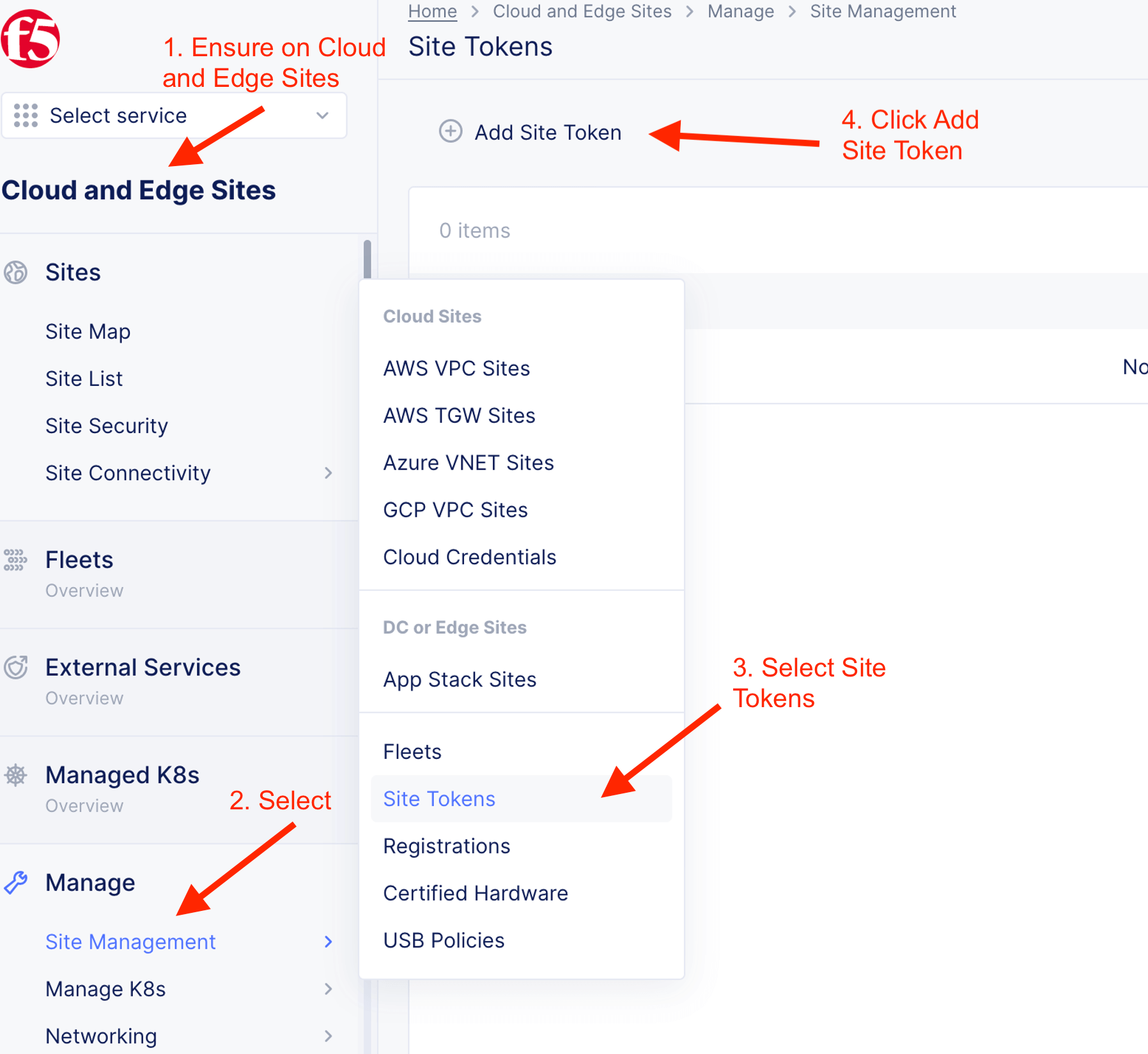
Step 1: Create Site token
You can always click F5 logo on top right to go to main screen.
Input your own token name. For example, if you been allocated with CE name of “ce-01”, your token name will be “ce-01-token”
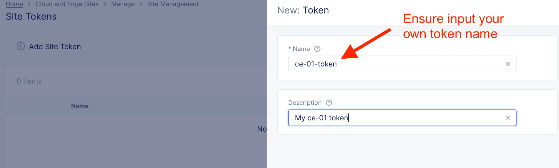
Token generated and will be use for subsequence step

Step 2: Enroll CE Node
2.1 Start CE node enrollment
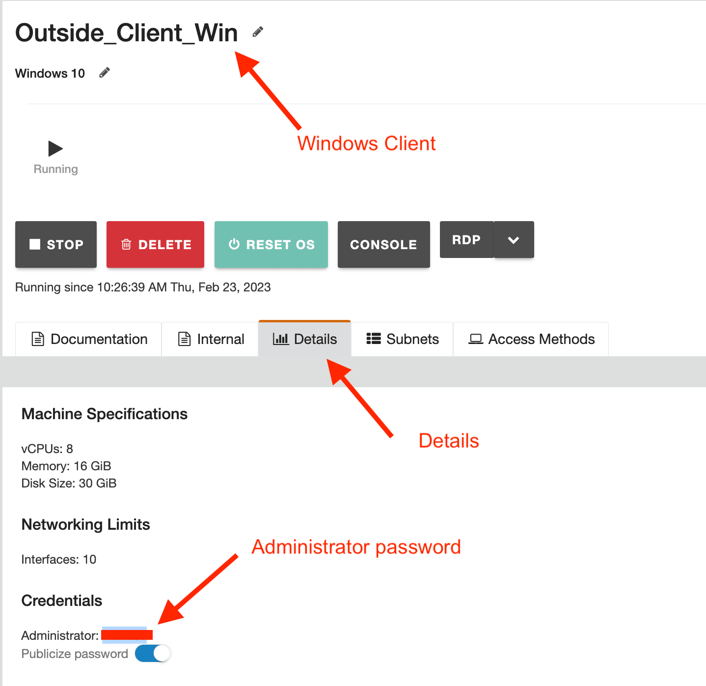
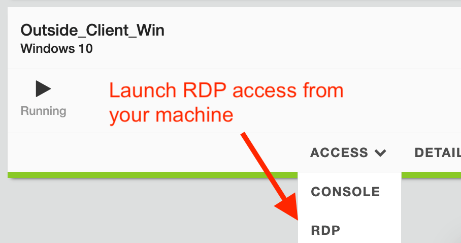
From UDF main page, RDP to Windows Jumphost
Username and password will be provided or obtains from UDF Details tab.
Perform subsequent task from Windows Jumphost
SSH to CE node with PuTTY and select “master-0”.
Below are info of CE node
| master-0 | 10.1.1.4 |
| master-1 | 10.1.1.5 |
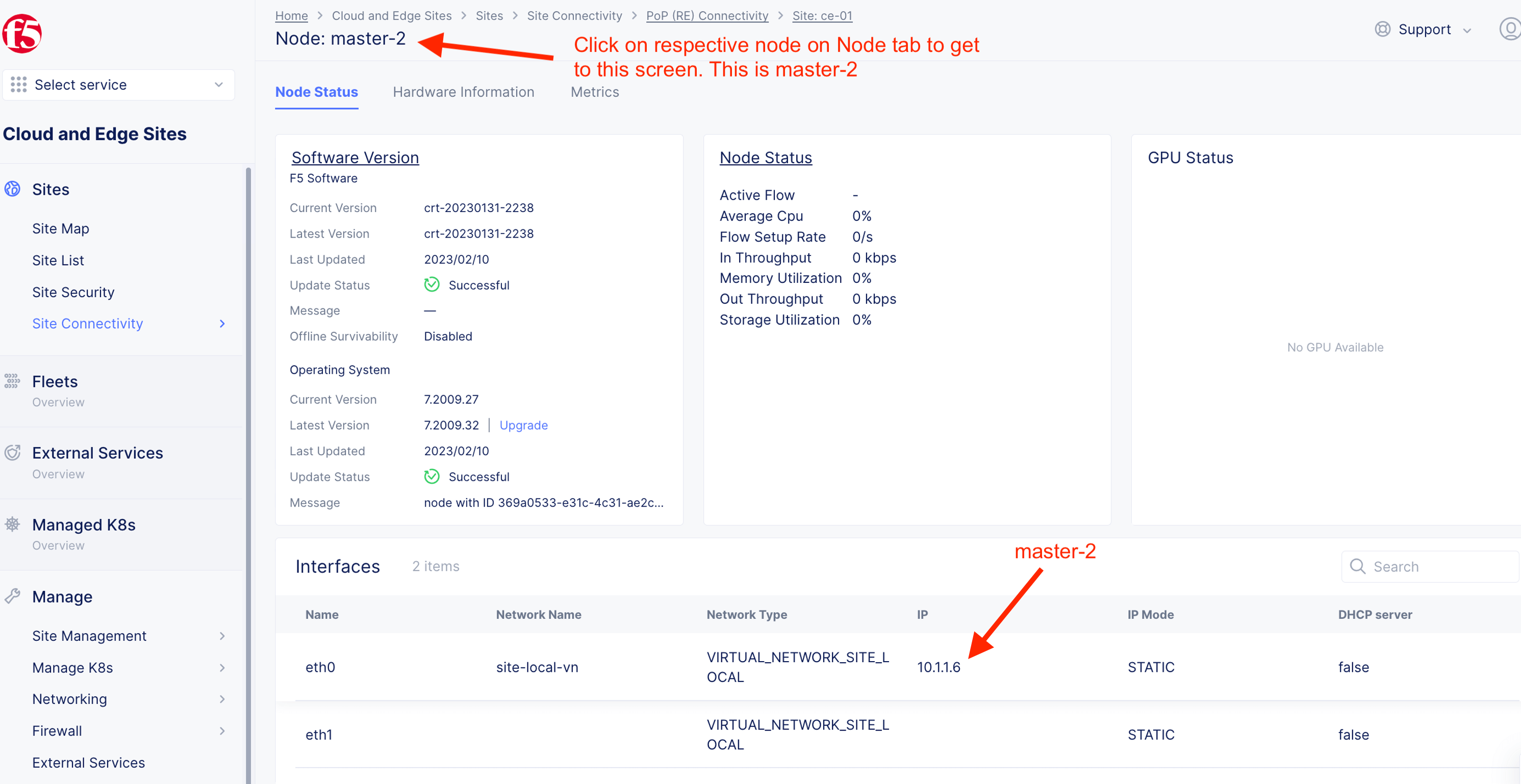
| master-2 | 10.1.1.6 |

Login with the following default credential
| Username | admin |
| Password | Volterra123 |
You are required to change admin password on first time login.

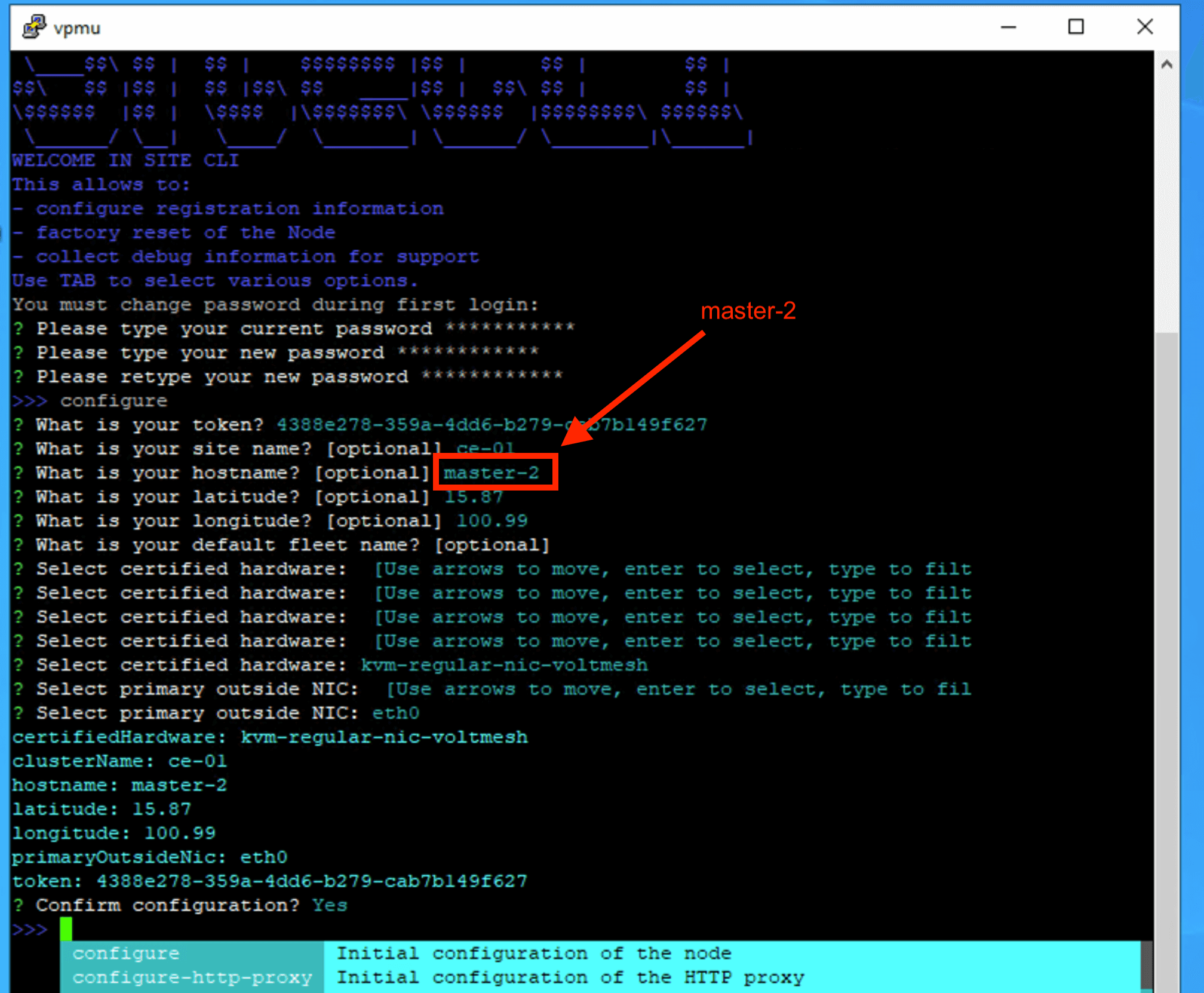
Input the following details
| Value | |
|---|---|
| Token | Token value generated from previous steps |
| Site Name | Your CE site name (e.g. ce-01, ce-02, ce03, etc) |
| Hostname | Hostname for the node. Use “master-0, master-1 or master-2, worker-0, etc” |
| Latitude | Optional latitude. Determine registration to RE |
| Longtitude | Optional longtitude. Determine registration to RE |
| Default Fleet name | Optional. Leave it blank |
| Certified Hardware | kvm-regular-nic-voltmesh |
| Primary NIC | eth0 |
Enter to confirm configuration.
Example

2.2 Approve Registration
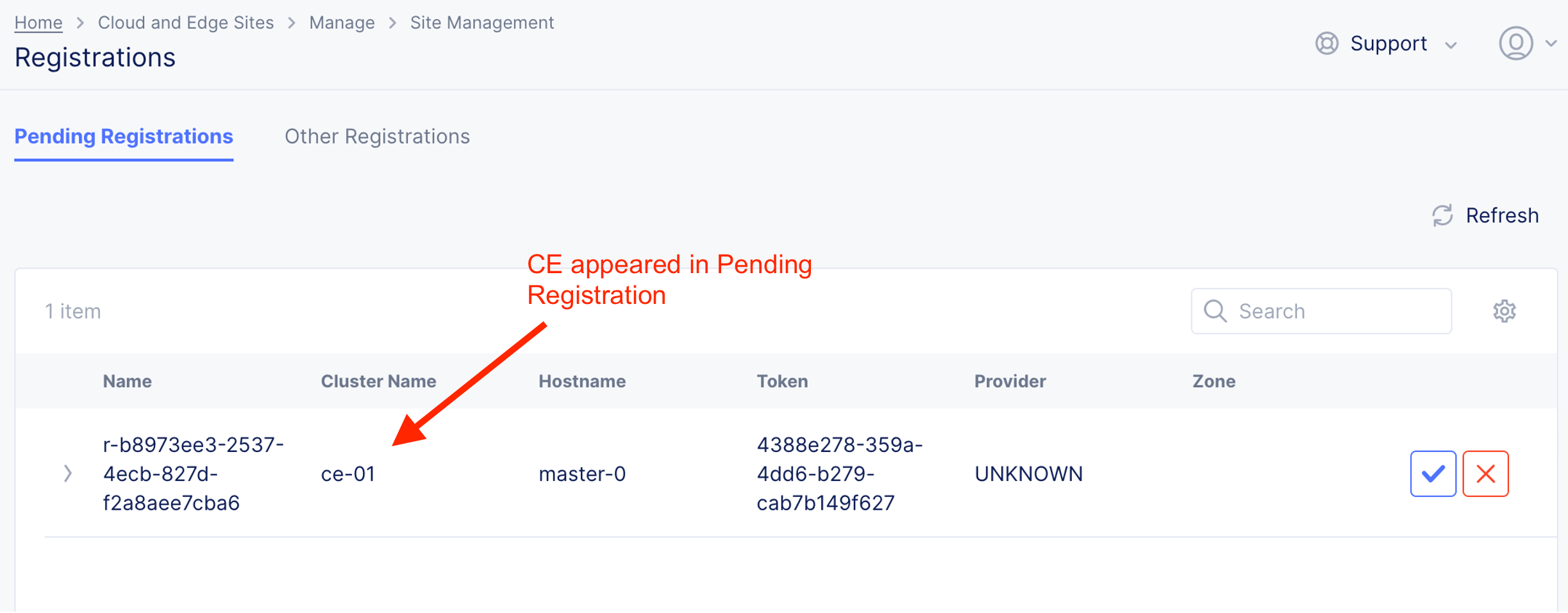
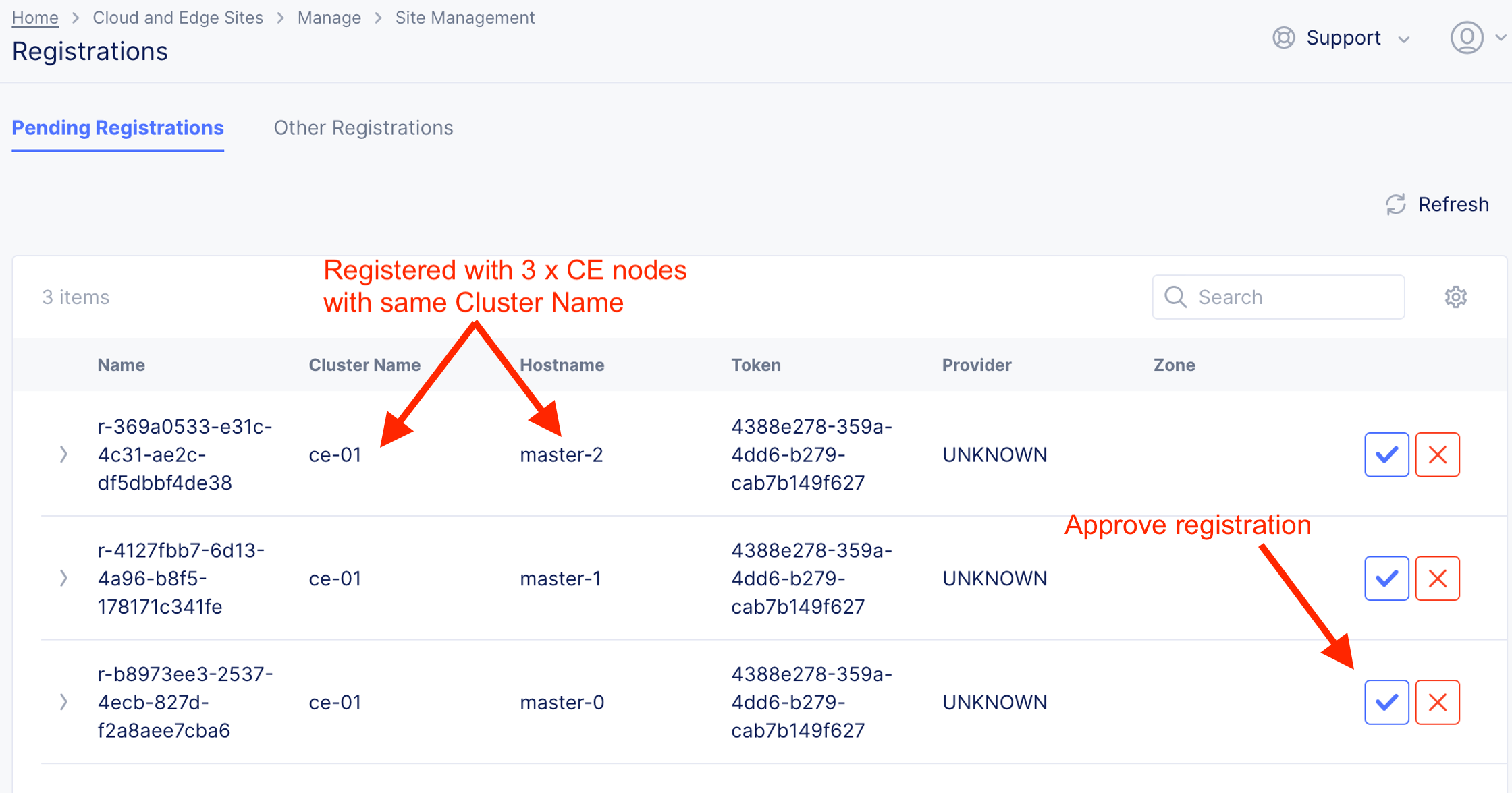
Upon successful registration of CE onto F5XC Console, CE node will appear in F5XC Console

UI shown CE node in “Pending Registrations”. Administrator approval to enroll is required.
Important
DO NOT approve registration if you are doing a multi-node CE cluster. For multi-node cluster, you will need to wait until all 3 node being enrolled. If you are doing a single node cluster, you CAN approved here now.
Note
Depend on class instruction. For CE cluster with HA setup, proceed with Cluster Setup steps. Else, skips to “Approve CE node registration”
2.3 Cluster Setup
Note
This steps only require if you setup a CE Cluster with HA - 3 CE nodes cluster
CE node cluster runs with minimum 3 nodes.
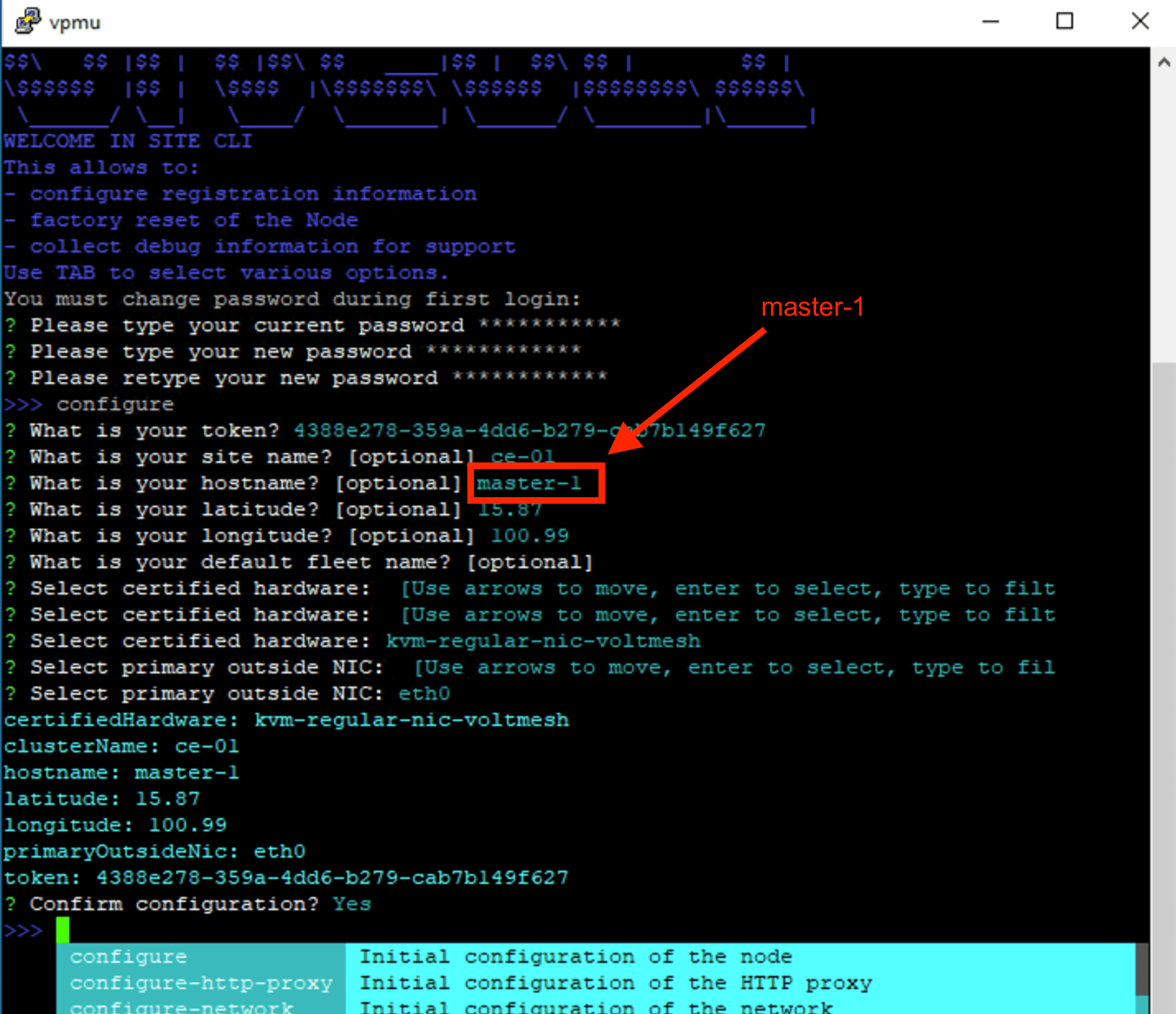
Enroll master-1
SSH via PuTTY to master-1
Repeat same CE enrolment process. You only required to change hostname value. Other value remain the same.
Enroll master-2
SSH via PuTTY to master-2
Repeat same CE enrolment process. You only required to change hostname value. Other value remain the same.
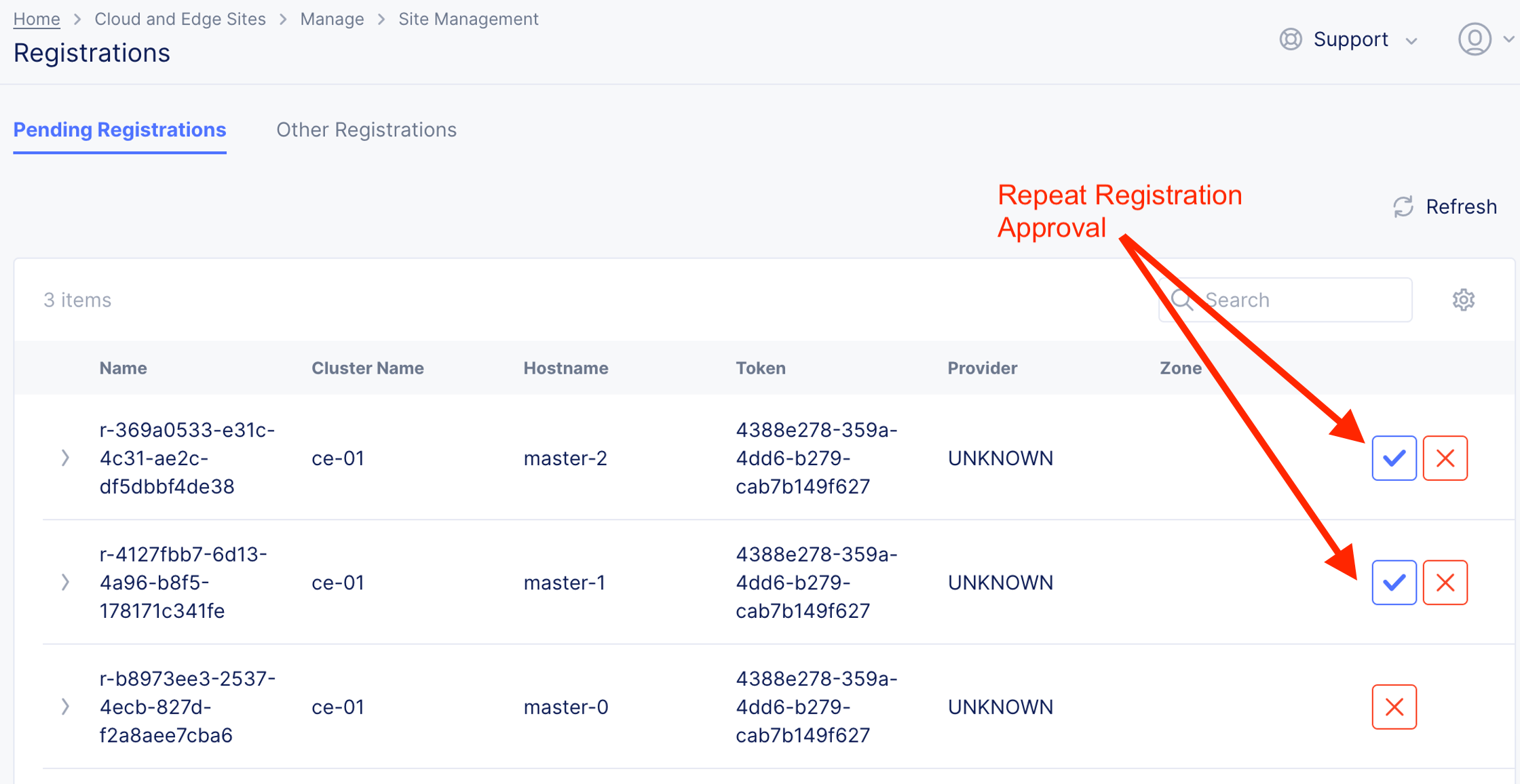
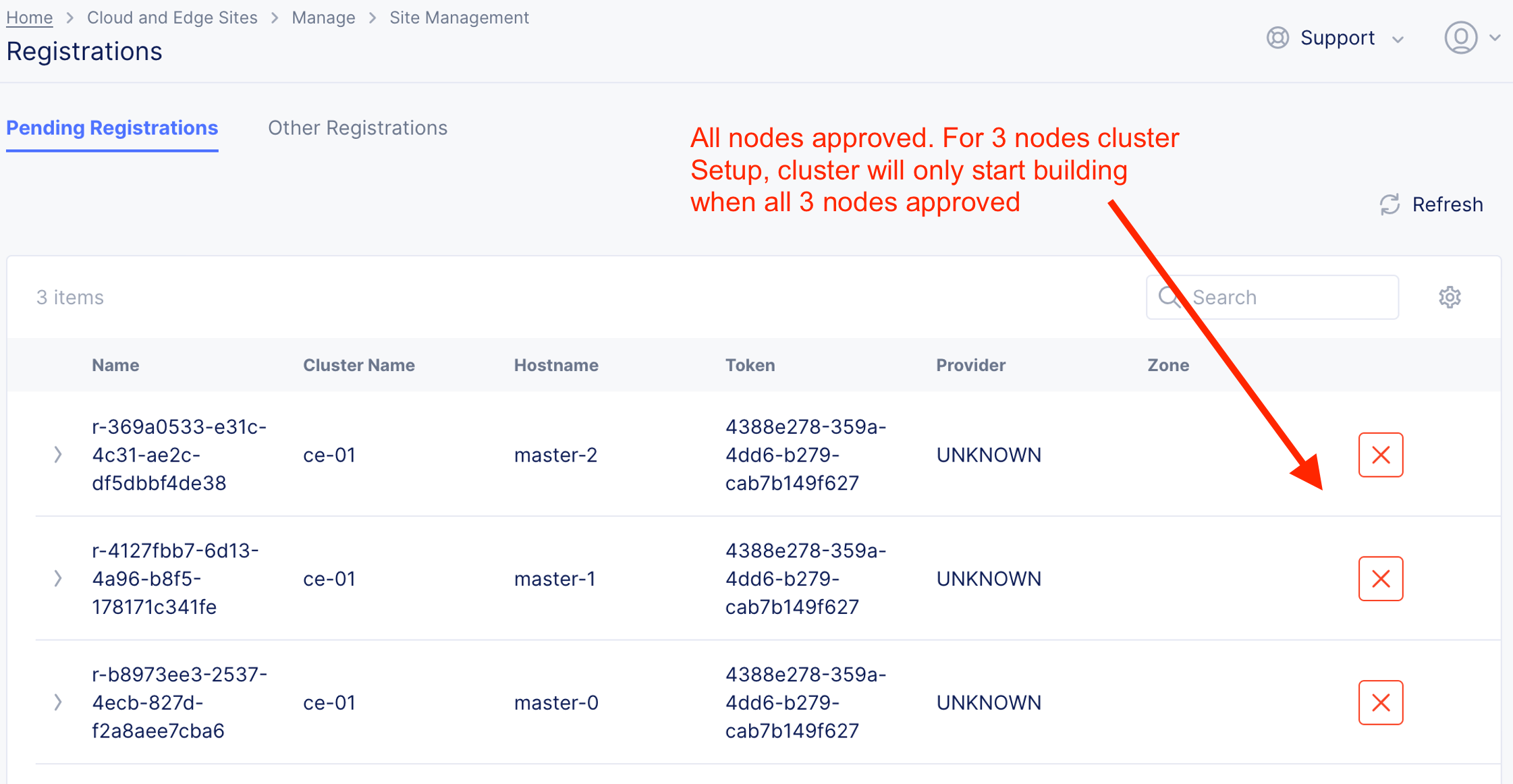
2.4 Approve CE node registration
From F5XC Console, approve pending registrations
Note
Image shown below with CE Cluster with HA. You may only see CE Cluster with single node (e.g. master-0 only).
For Single node CE, Cluster Size will be “1” and for Multi-Node CE (CE Cluster with HA), Cluster size will be “3”.
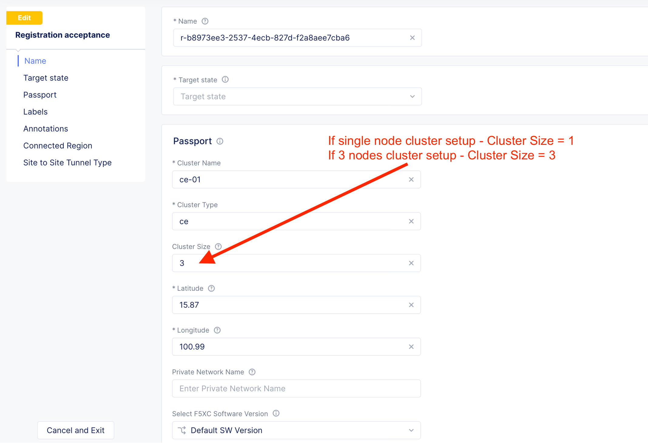
With CE cluster with HA, all 3 nodes have to be approved and present before CE cluster provisioning started.
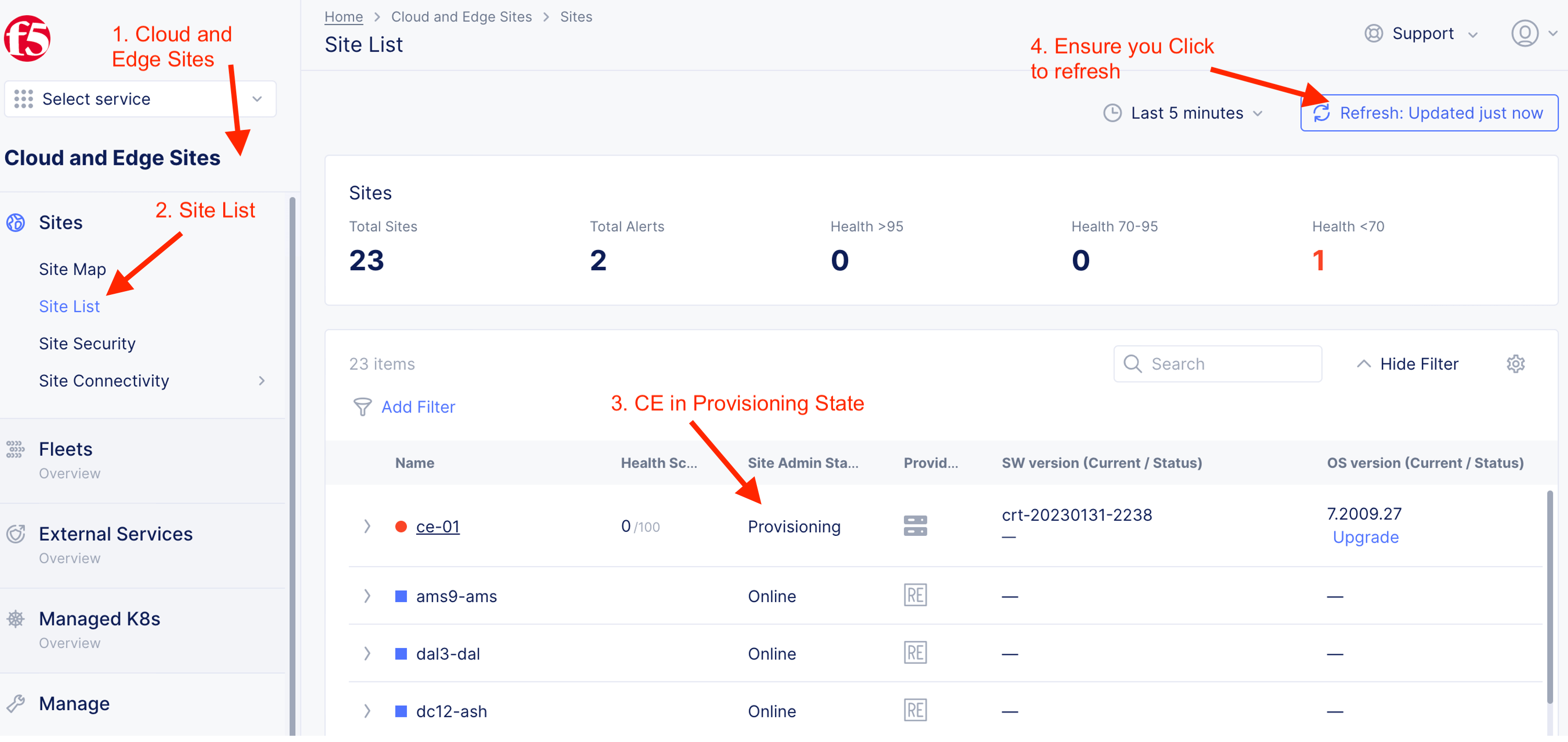
2.5 CE Cluster onboarded and healthy
CE in “Provisioning” State
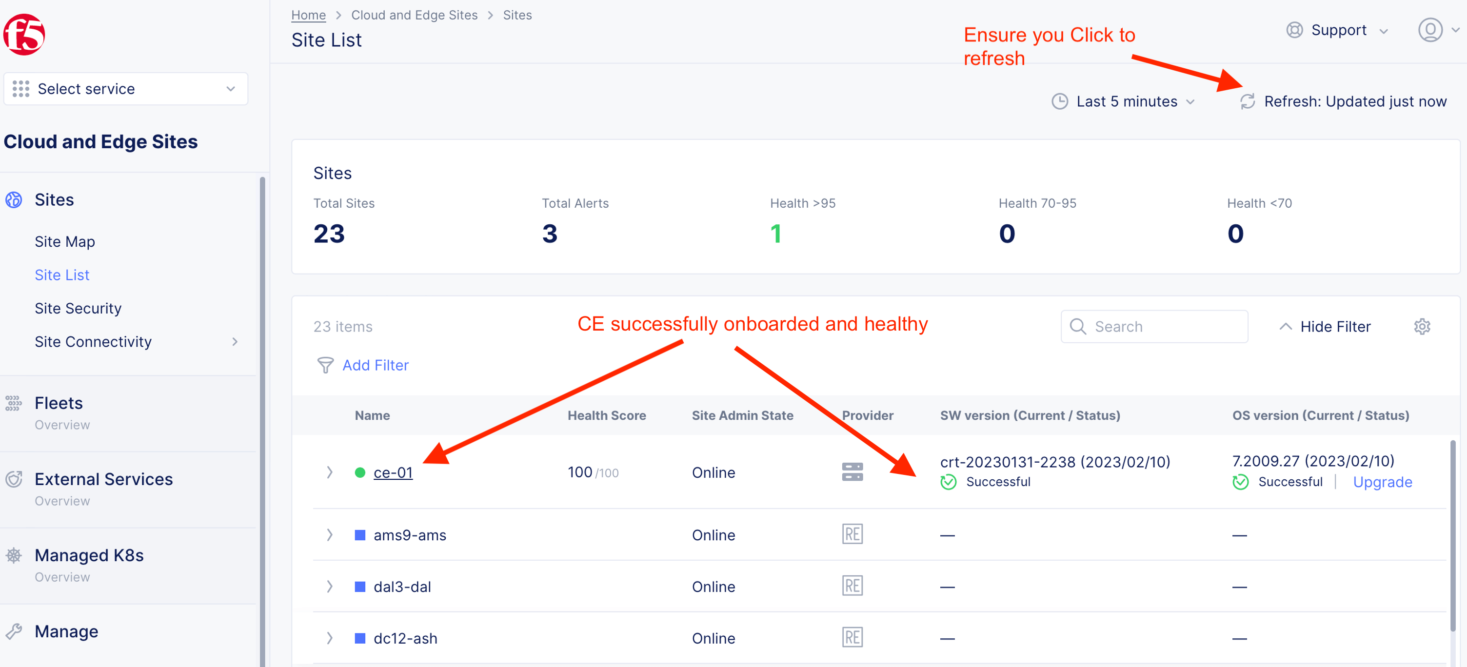
CE in “Healthy” State
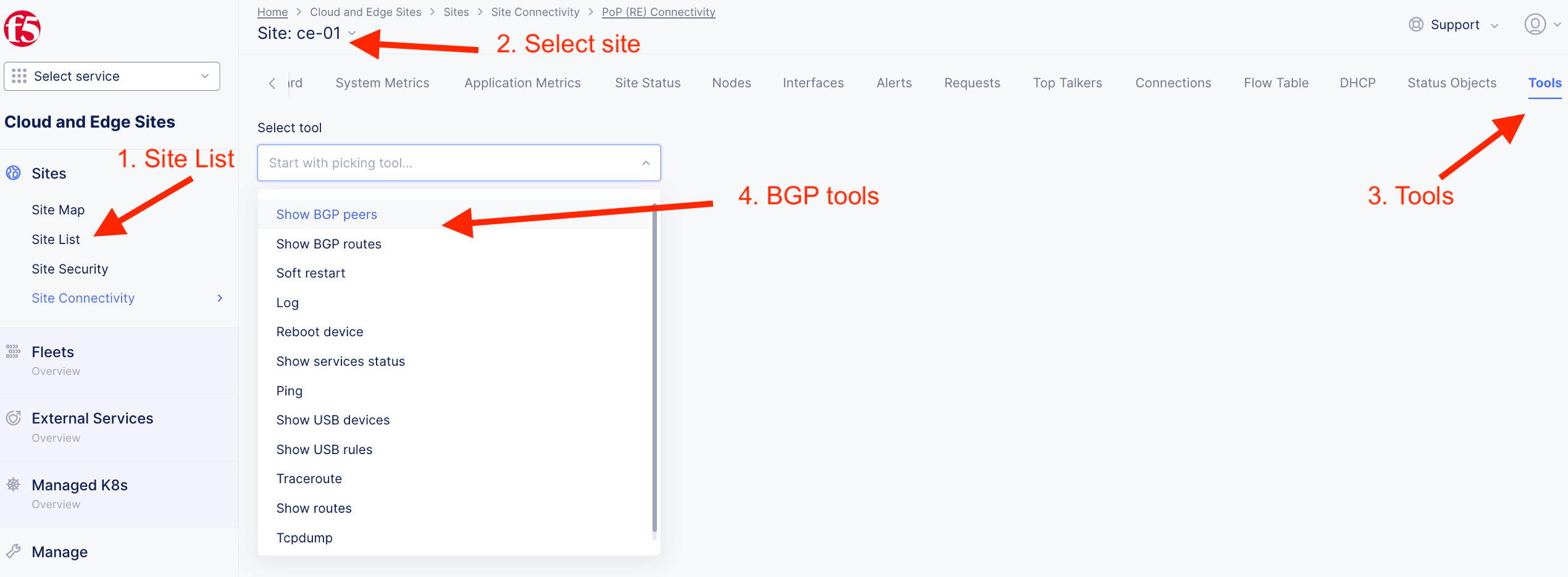
Step 3: Explore CE Status
Dashboard - CE-01

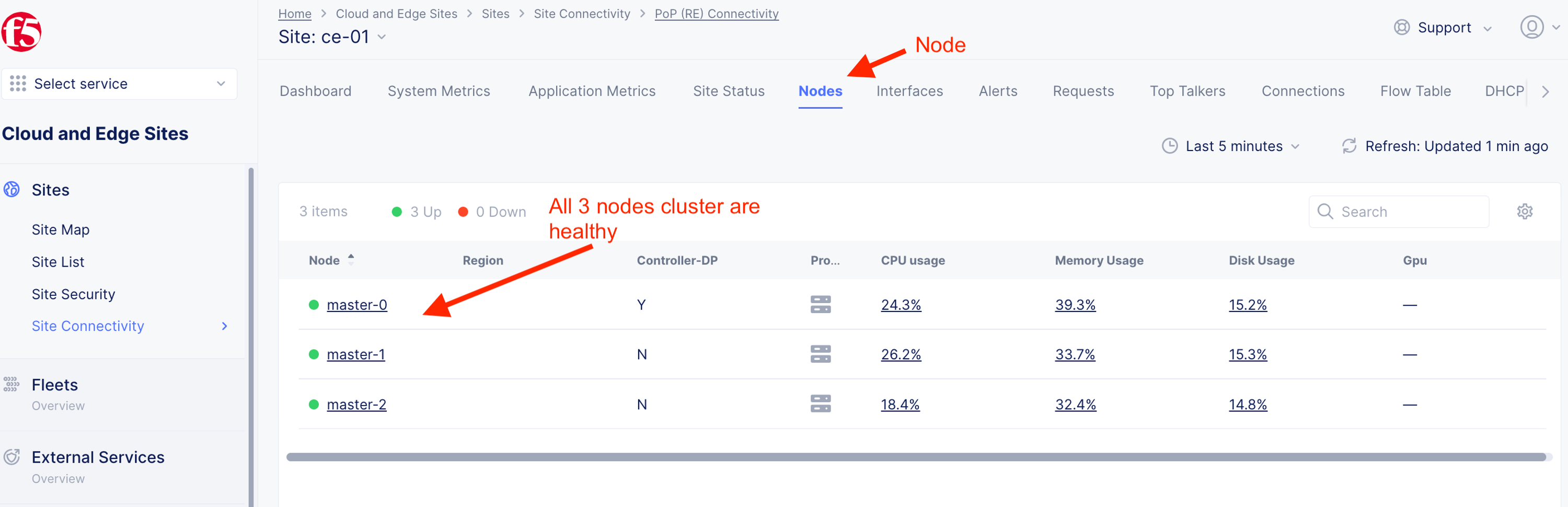
Nodes - CE-01
Site Status - CE-01

Node: master-0

Node: master-1

Node: master-2
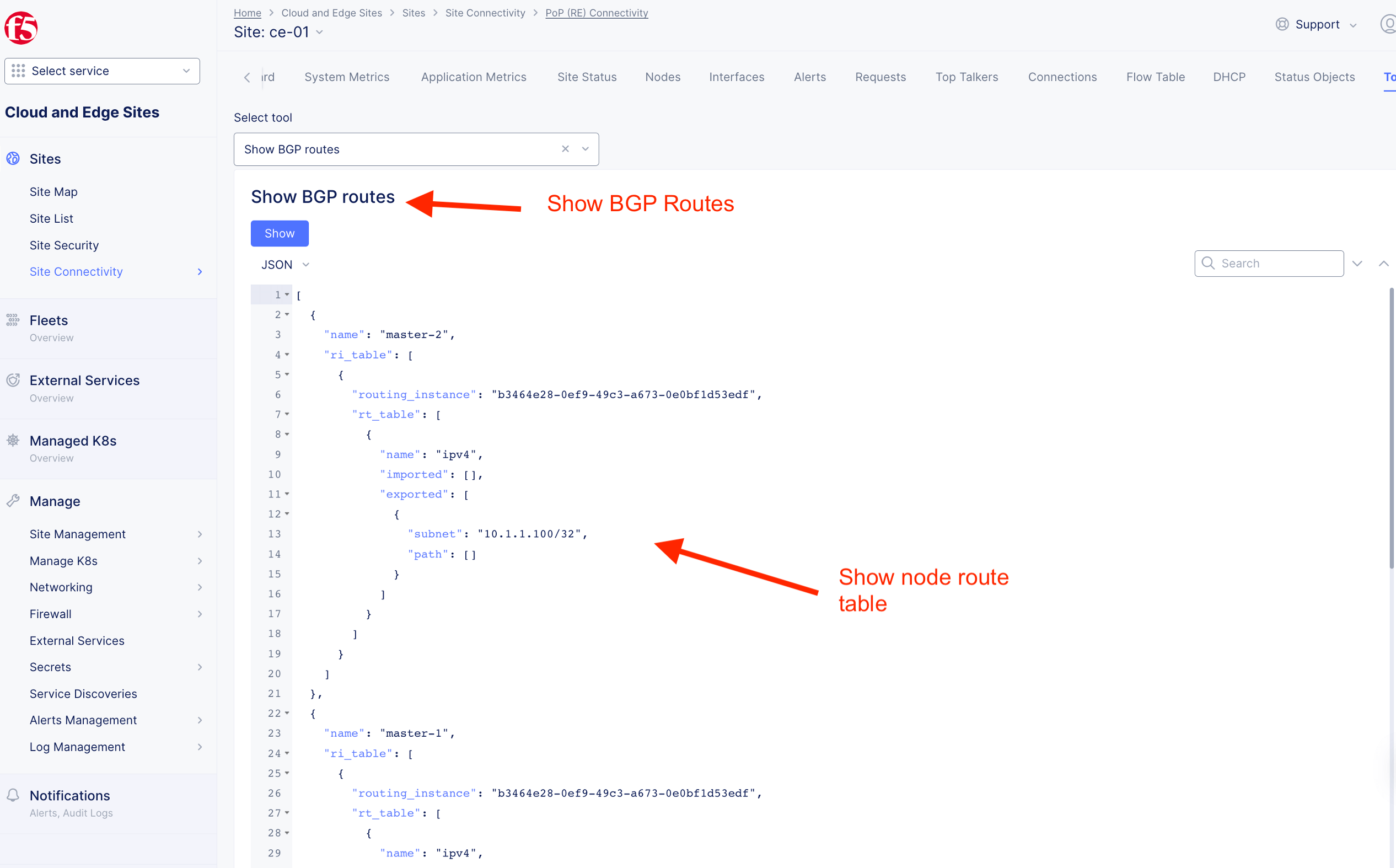
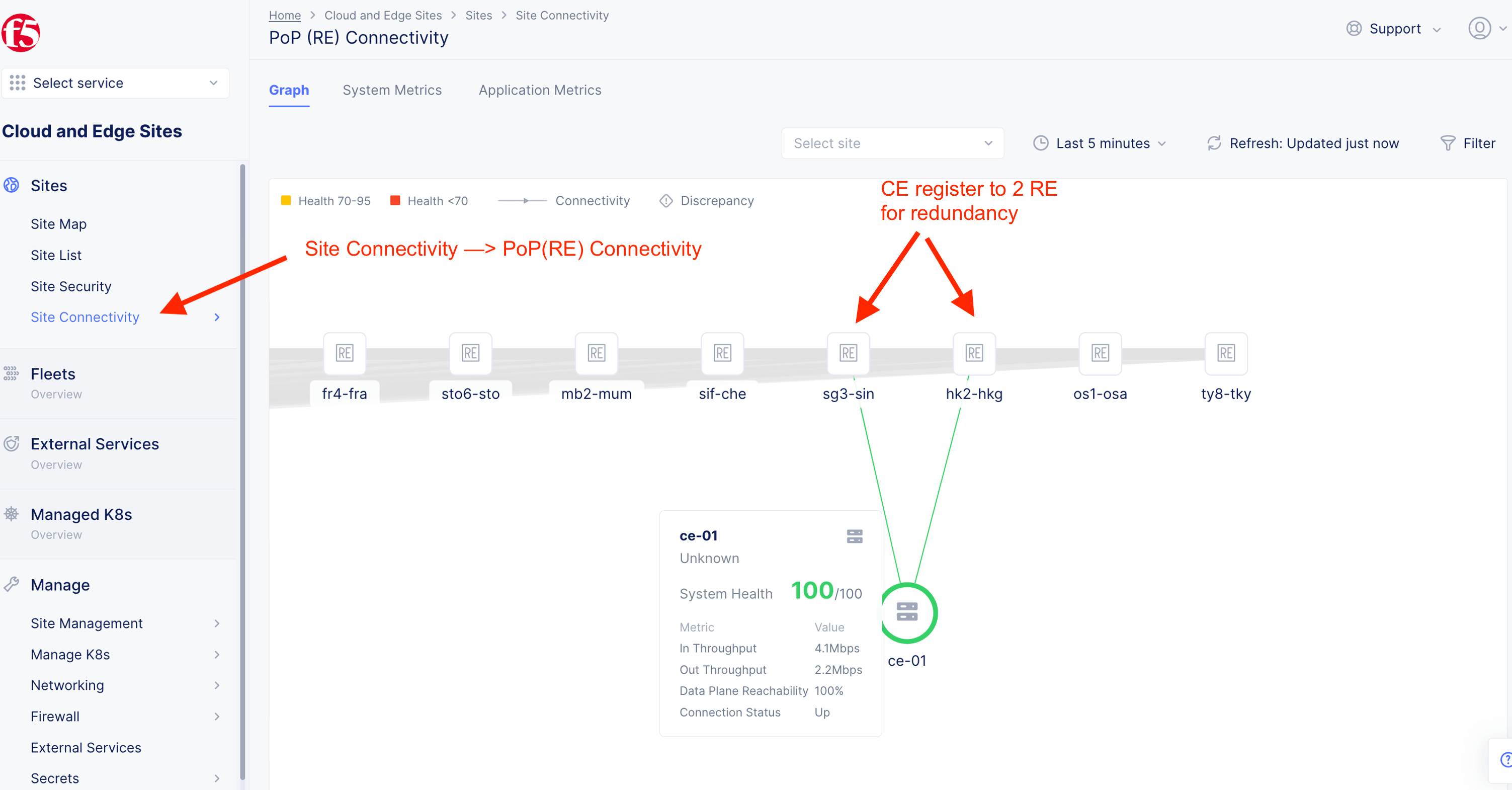
PoP(RE) Connectivity - CE-01
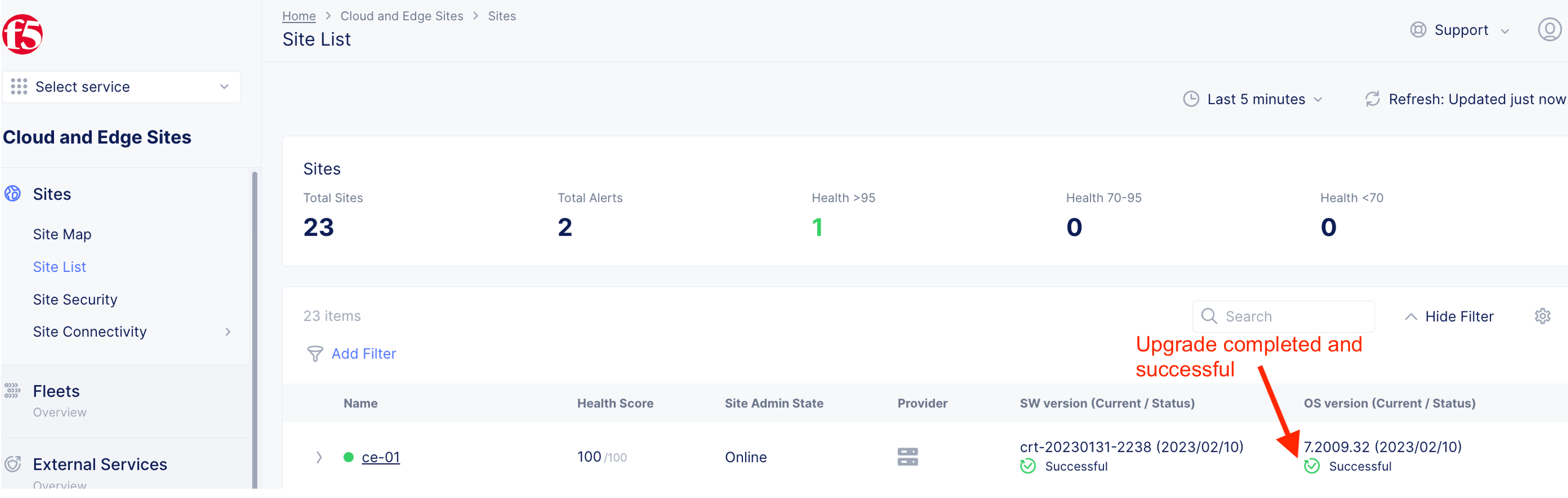
Step 4: Update and Upgrade Node
CE software are built on demand. Hence, it always uses the current version. OS is depends on the original iso or ova file.
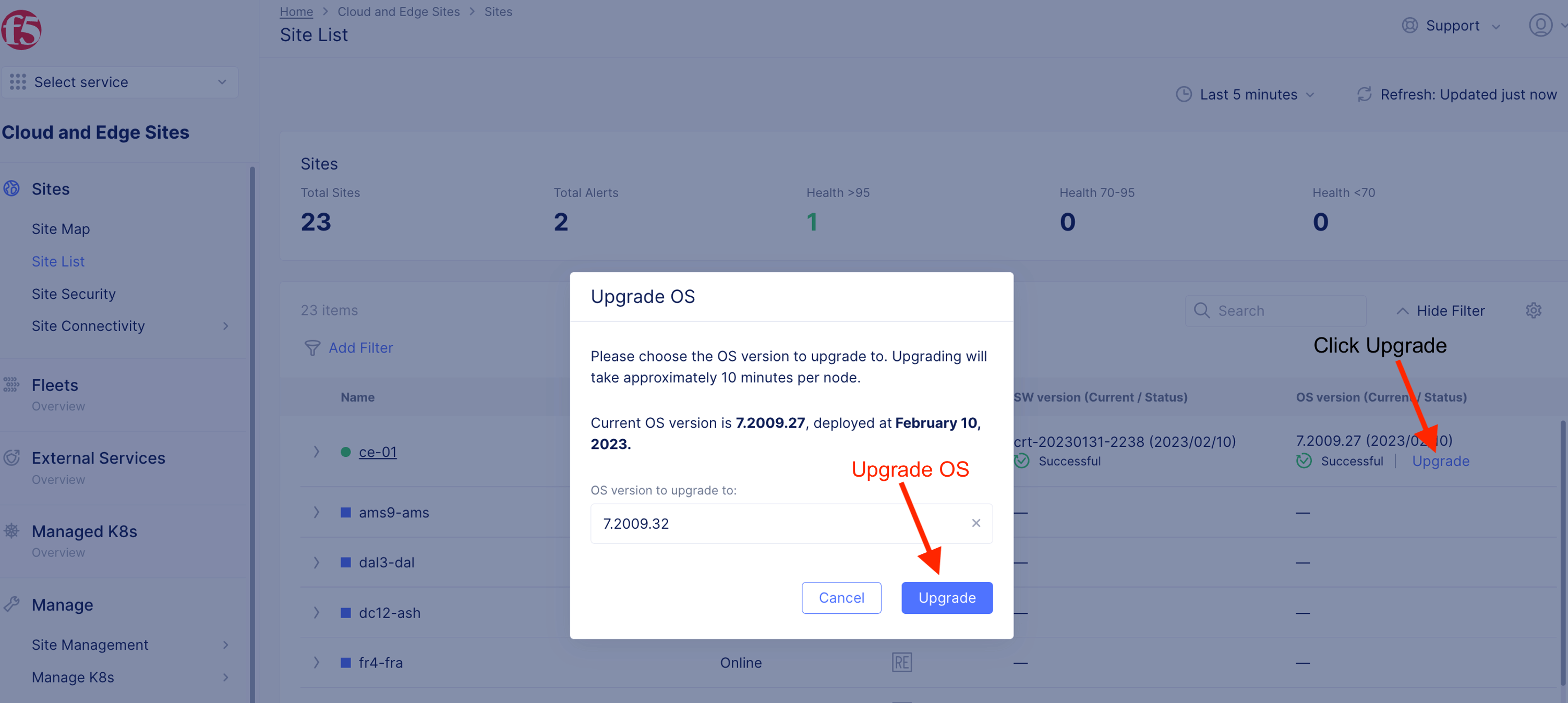
Click upgrade to upgrade CE OS.
CE schedule to be upgraded. In a mult-node CE, F5XC intent-based orchstration will upgrade one CE node at a time. Health of a CE node will be validated (Ready) before second node will be upgrade. That will ensure minimum downtime during the OS upgrade.
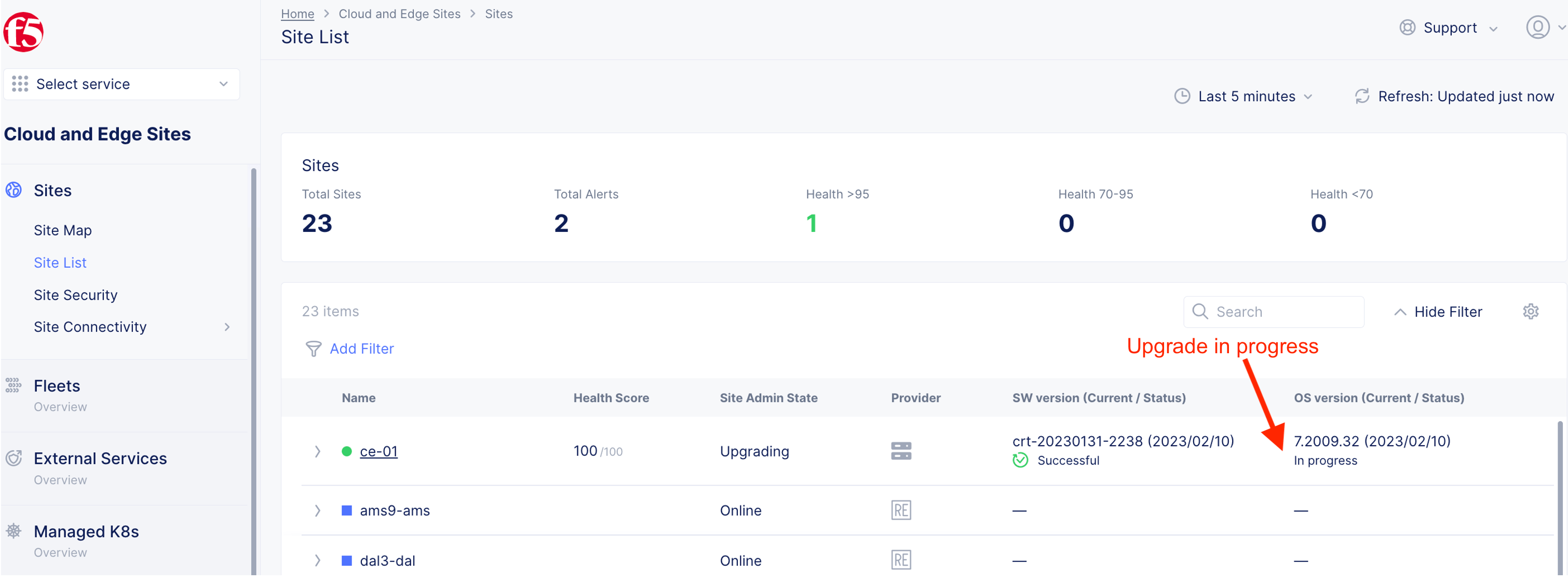
CE node(s) successfully upgraded and healthy.
Step 5: Setup Cluster VIP
Specify a cluseter IP (VIP). This is in additional to the CE node IP.

Note
Cluster VIP is not pingable/alive until a HTTP/TCP LB created to advertise that cluster VIP.
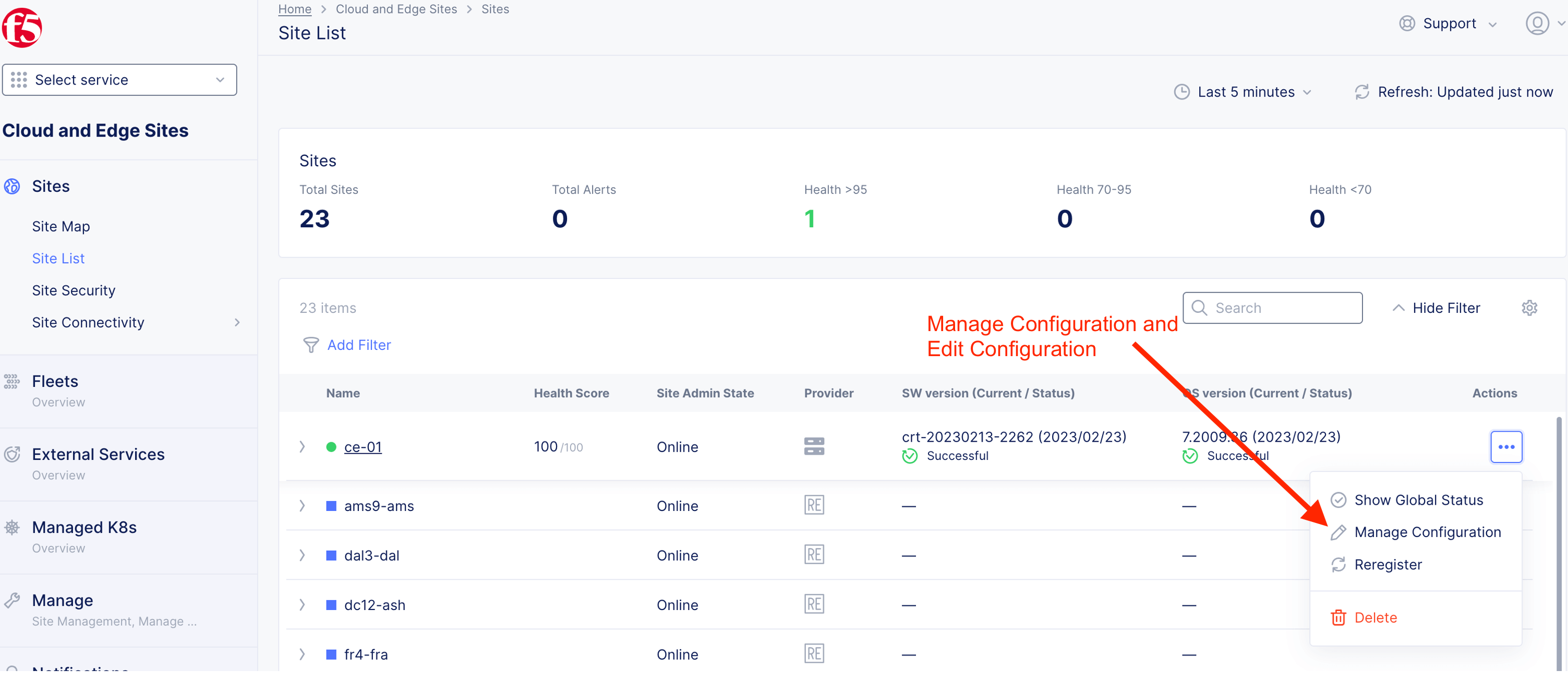
Step 6: Create Fleet
4.1 Create interface
Note
For the purpose of this lab, we will experience using 3 different methods to create Interface object. You can create all three interfaces using any of the following method.
- Click-Ops - Clicking from F5XC Console UI (for master-0)
- Clone from existing object (for master-1)
- Copy and Paste from a JSON config (for master-2)
Note
Replace any reference on ce-01 to the name of your own ce name (e.g. ce-0X)
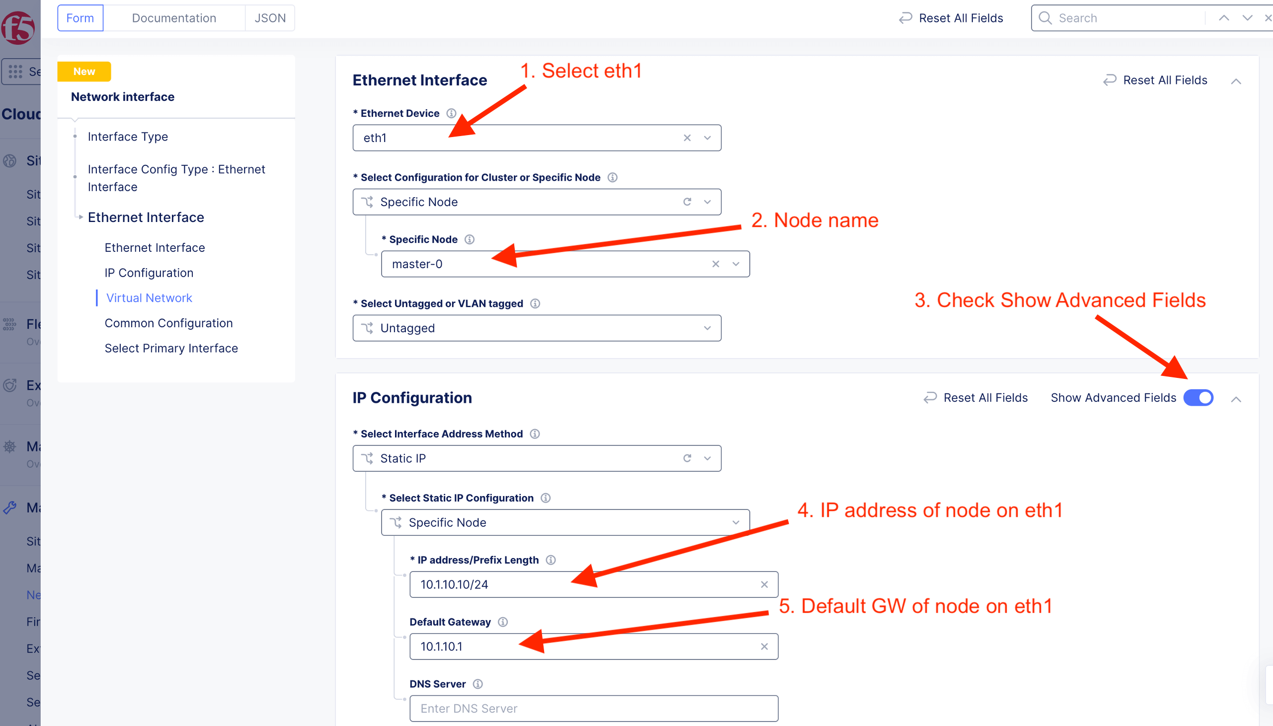
master-0-eth1 Interface (Click from UI)
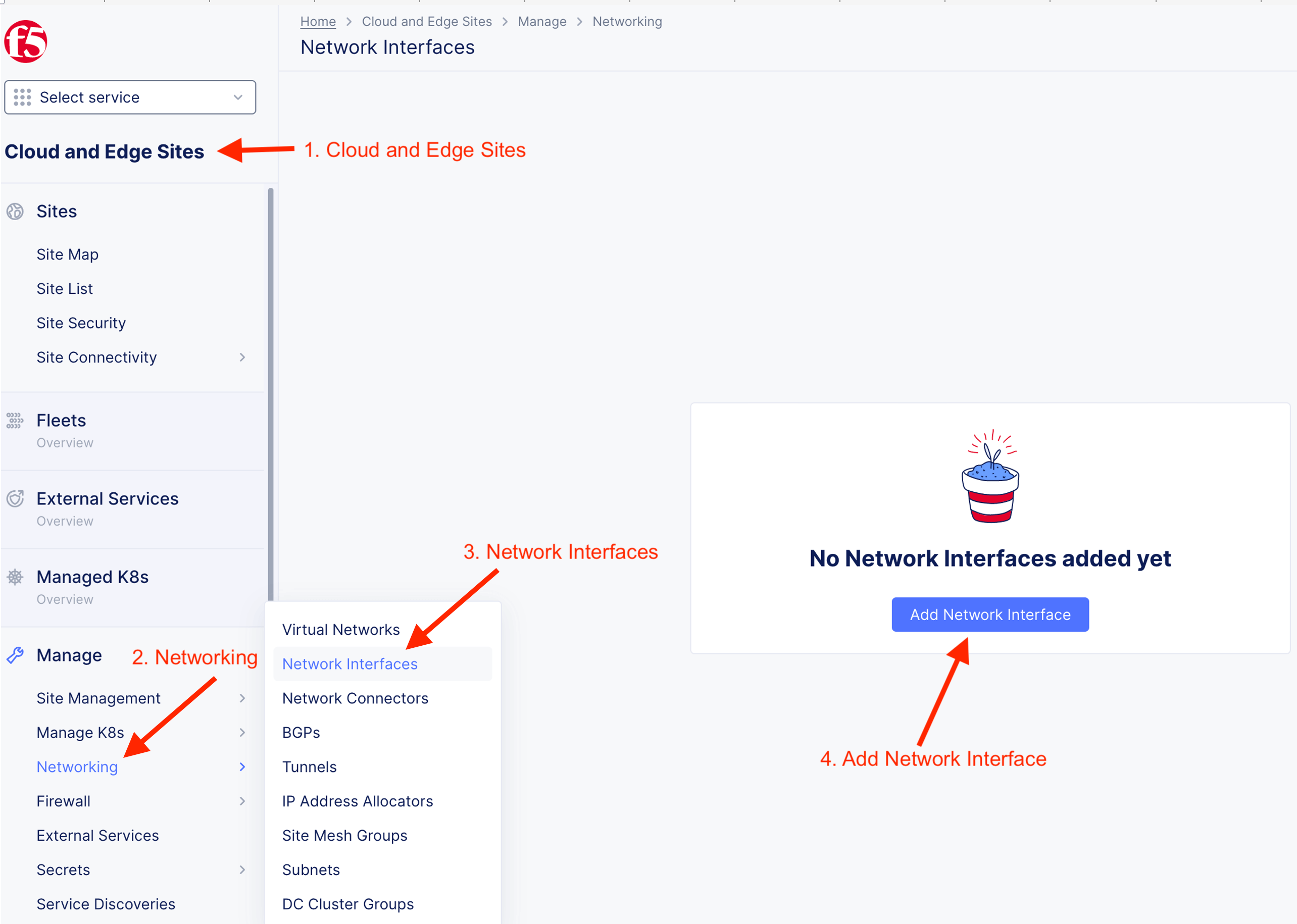
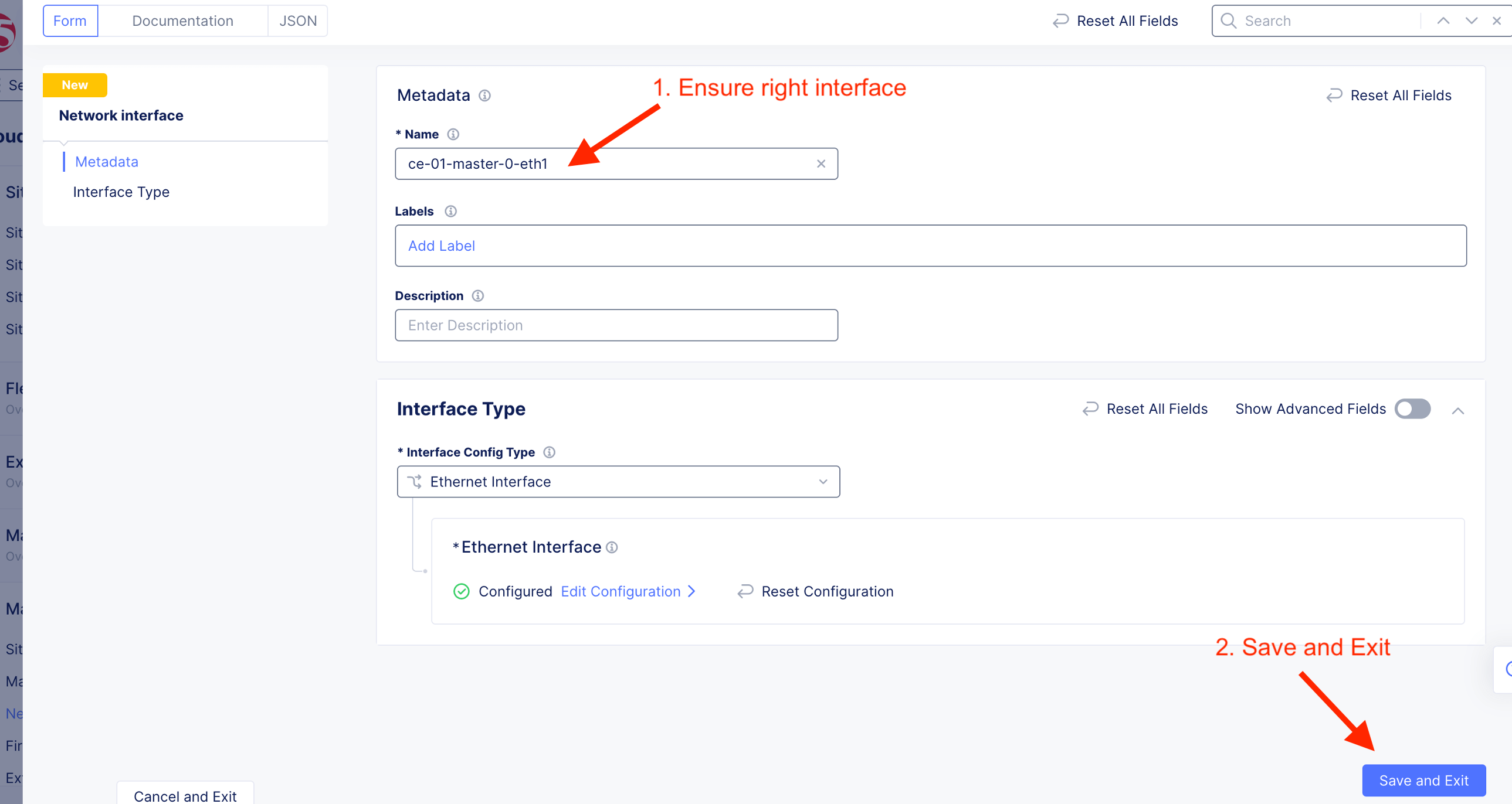
Specify Interface metadata
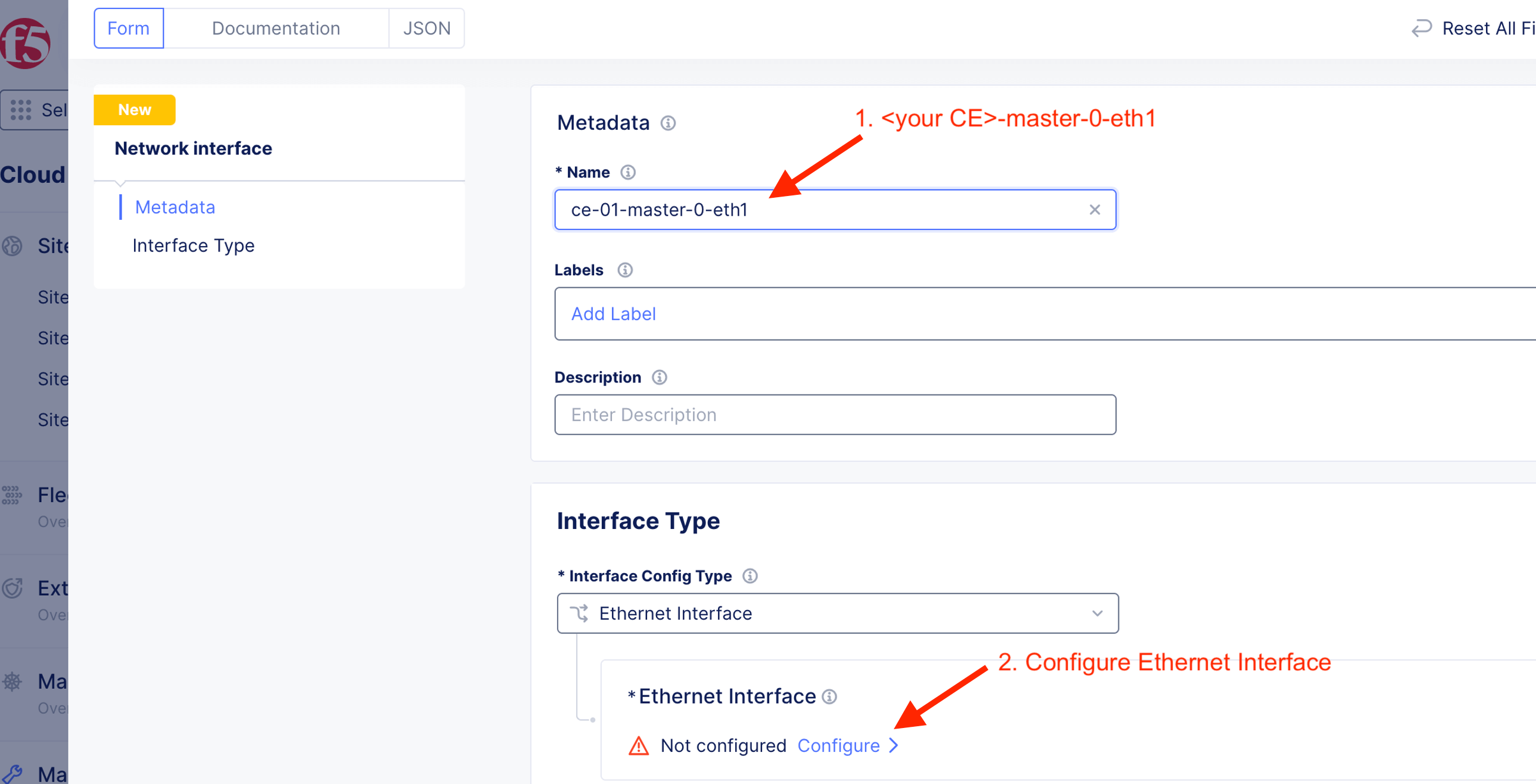
Specify Ethernet Interface information
Ensure select “Site Local Network Inside”
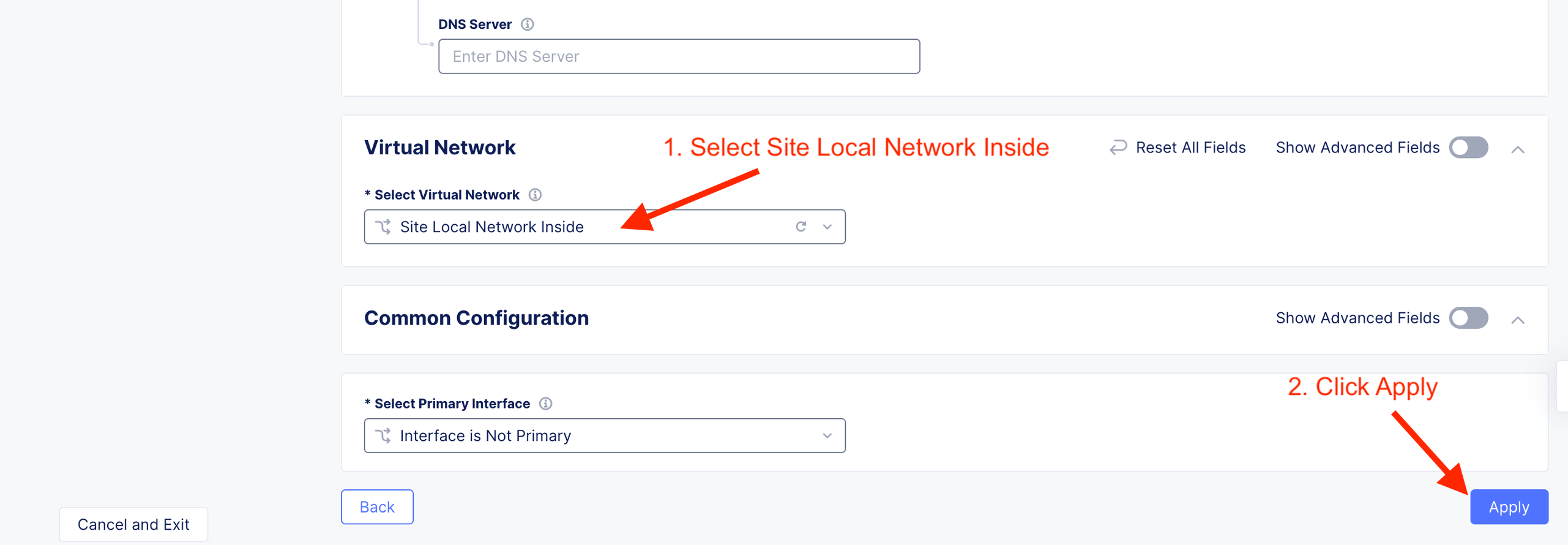
Save and Exit to confirm the configuration
master-1-eth1 (Clone from UI)

When you “Clone Object”, configuration (except Name) will be pre-populated. Ensure appropriate name.

Update to respective node hostname
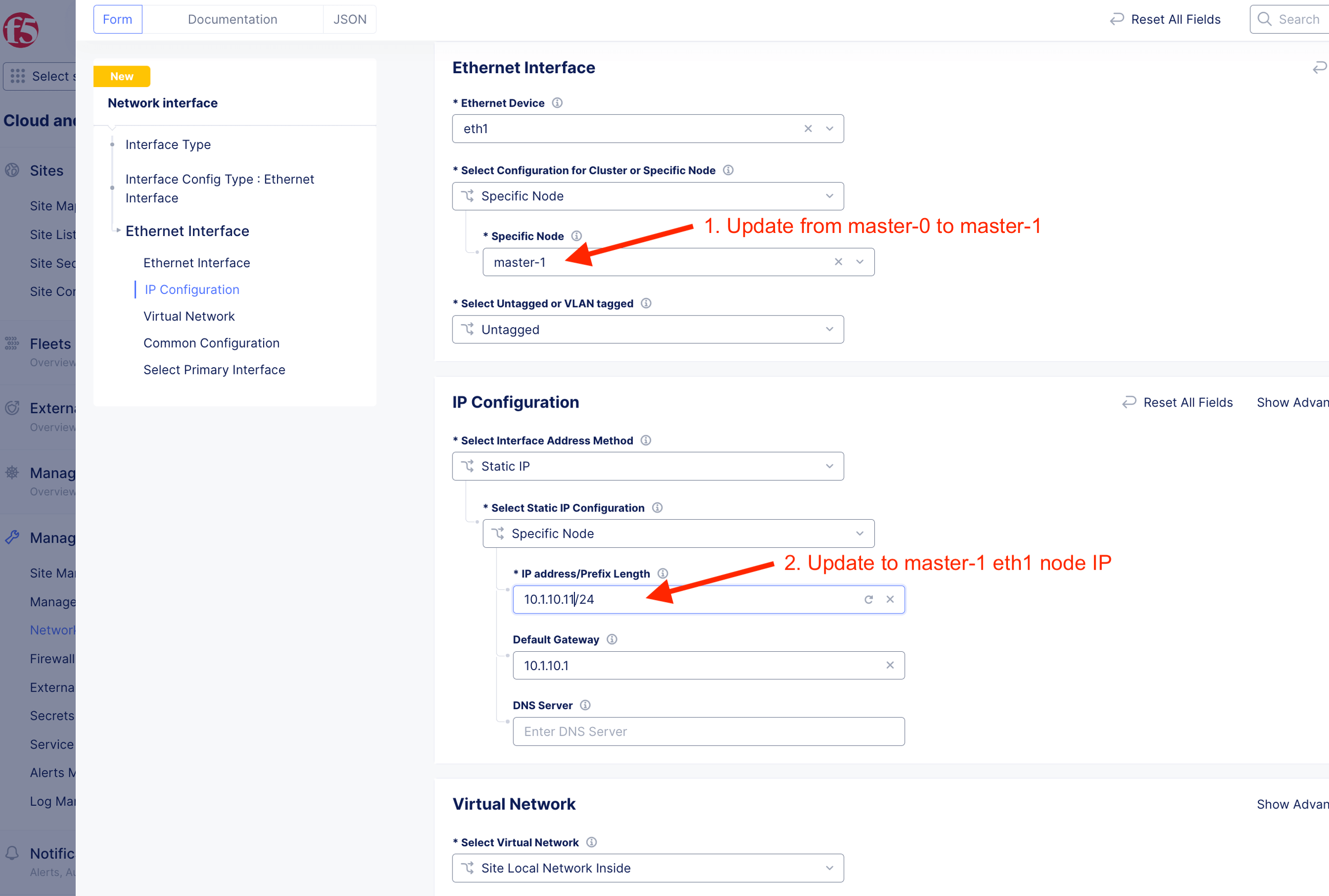
Save and Exit. Interface object will be created
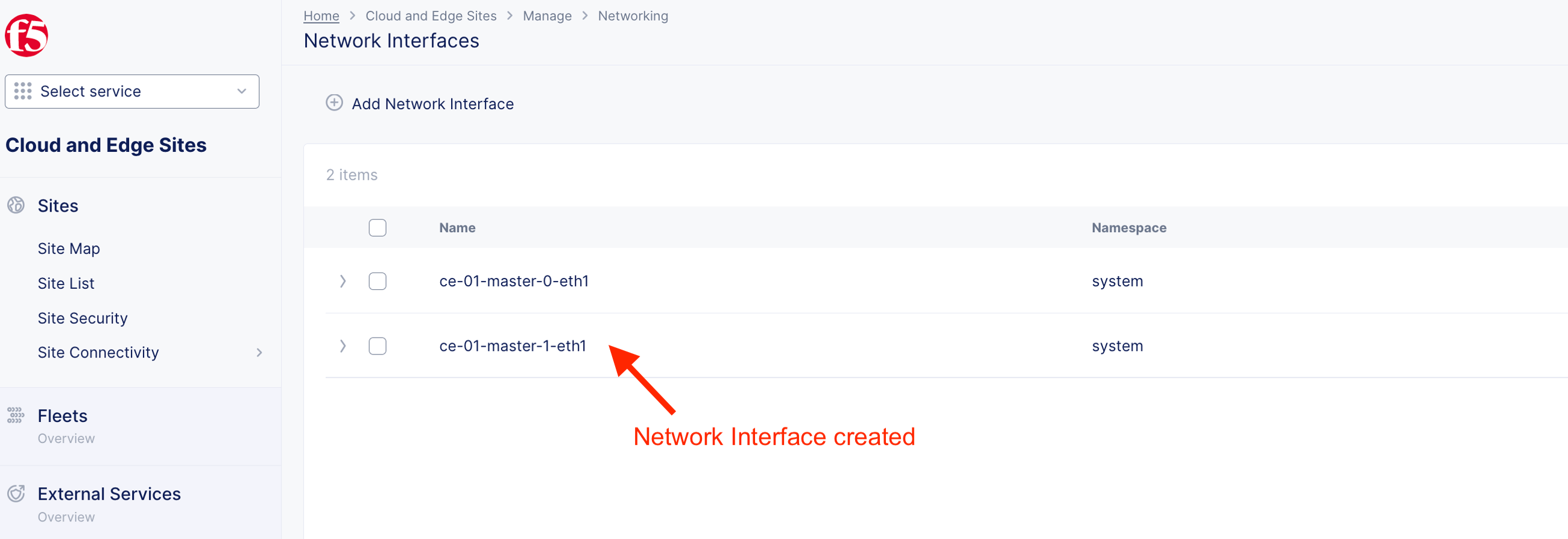
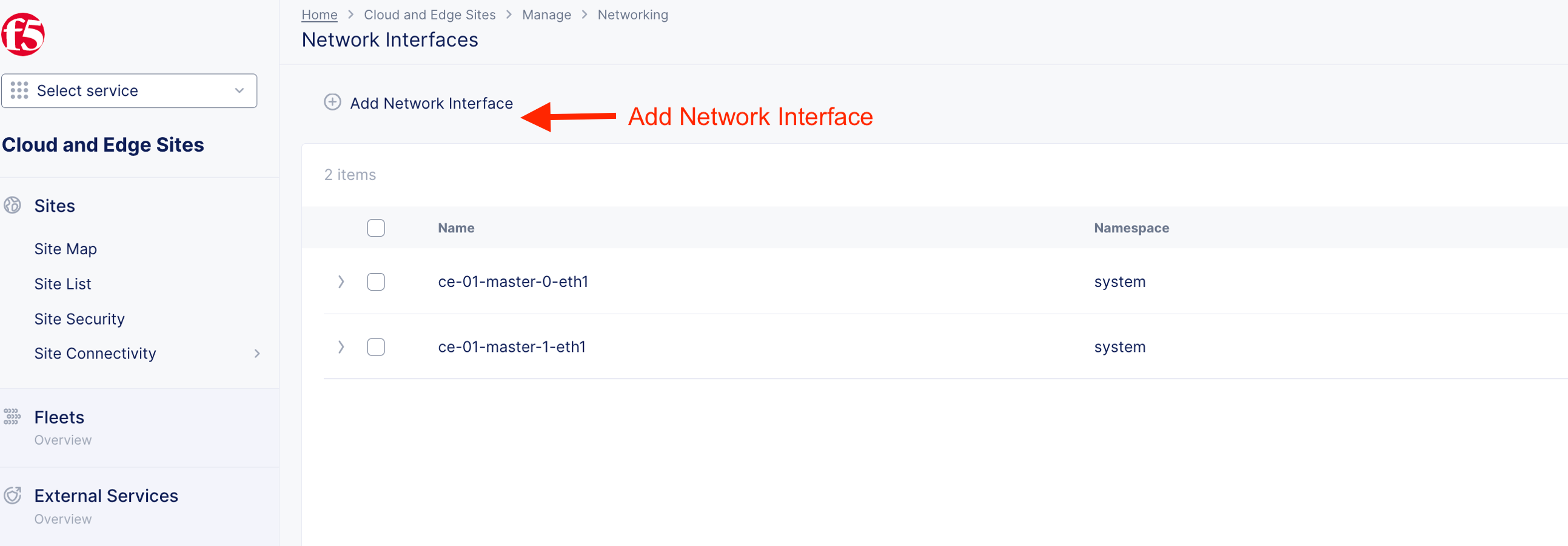
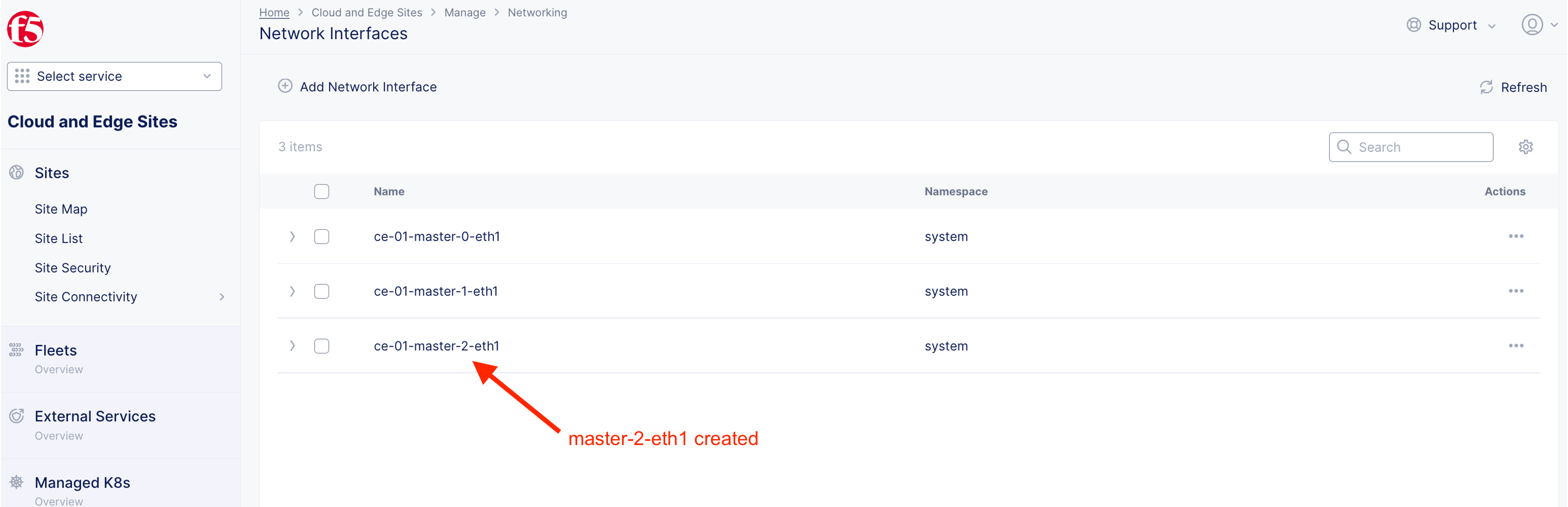
master-2-eth1 (Copy and paste)
JSON configuration for master-2-eth1 been prepared. Add Network interface.
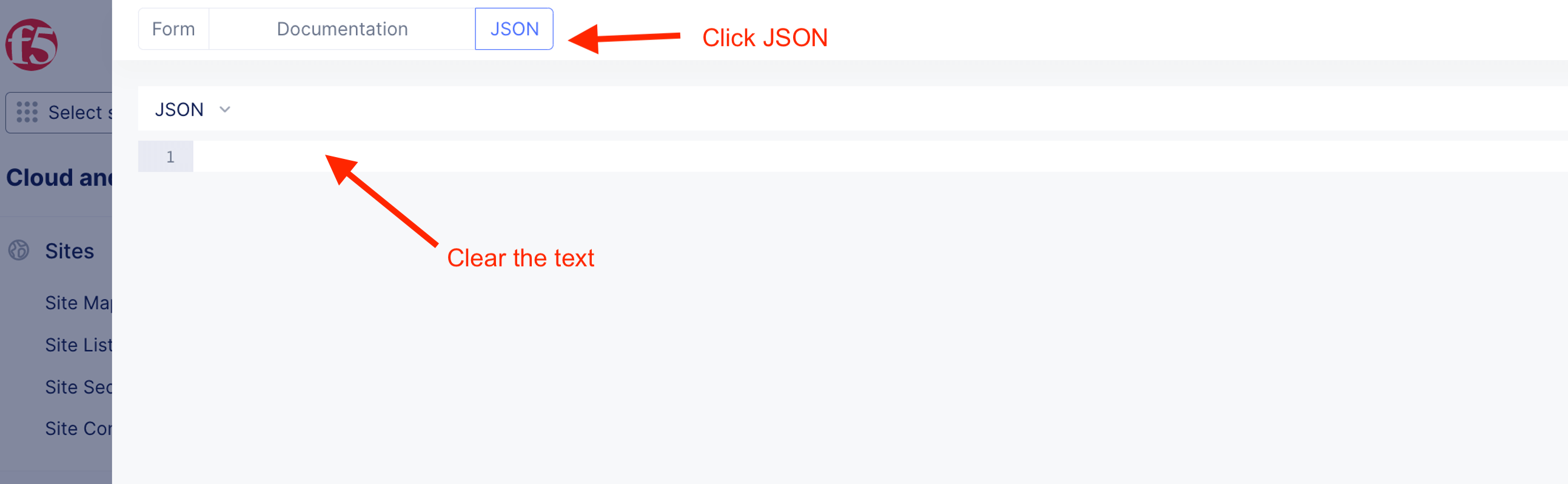
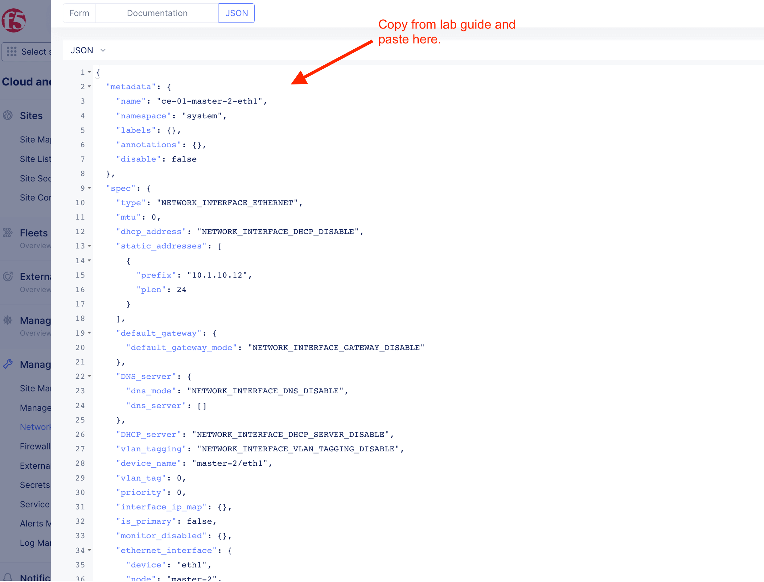
Clear/delete content in JSON and copy and paste the following prepared JSON configuration onto the text field.
ce-01-master-2-eth1
{
  "metadata": {
    "name": "ce-01-master-2-eth1",
    "namespace": "system",
    "labels": {},
    "annotations": {},
    "disable": false
  },
  "spec": {
    "type": "NETWORK_INTERFACE_ETHERNET",
    "mtu": 0,
    "dhcp_address": "NETWORK_INTERFACE_DHCP_DISABLE",
    "static_addresses": [
      {
        "prefix": "10.1.10.12",
        "plen": 24
      }
    ],
    "default_gateway": {
      "default_gateway_mode": "NETWORK_INTERFACE_GATEWAY_DISABLE"
    },
    "DNS_server": {
      "dns_mode": "NETWORK_INTERFACE_DNS_DISABLE",
      "dns_server": []
    },
    "DHCP_server": "NETWORK_INTERFACE_DHCP_SERVER_DISABLE",
    "vlan_tagging": "NETWORK_INTERFACE_VLAN_TAGGING_DISABLE",
    "device_name": "master-2/eth1",
    "vlan_tag": 0,
    "priority": 0,
    "interface_ip_map": {},
    "is_primary": false,
    "monitor_disabled": {},
    "ethernet_interface": {
      "device": "eth1",
      "node": "master-2",
      "untagged": {},
      "static_ip": {
        "node_static_ip": {
          "ip_address": "10.1.10.12/24"
        }
      },
      "no_ipv6_address": {},
      "site_local_inside_network": {},
      "mtu": 0,
      "priority": 0,
      "not_primary": {},
      "monitor_disabled": {}
    }
  }
}
Examle pasted content
Interface created
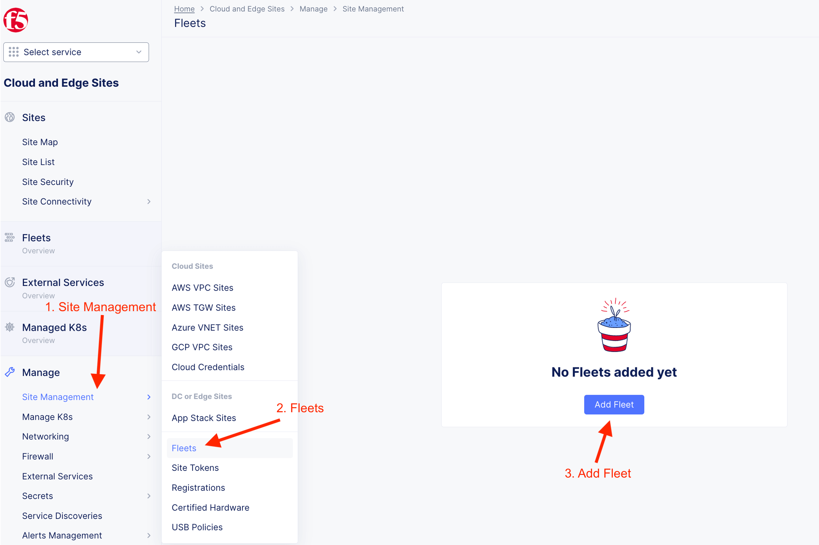
4.2 Create Fleet
Fleet is used to configure infrastructure components (like nodes) in one or CE sites homogeneously. Fleet configuration includes the following information
- Software image release to be deployed on the Fleet
- Virtual networks
- List of interface and devices to be configured on every node
- Connections between the virtual networks
- Security policies applied in the Site
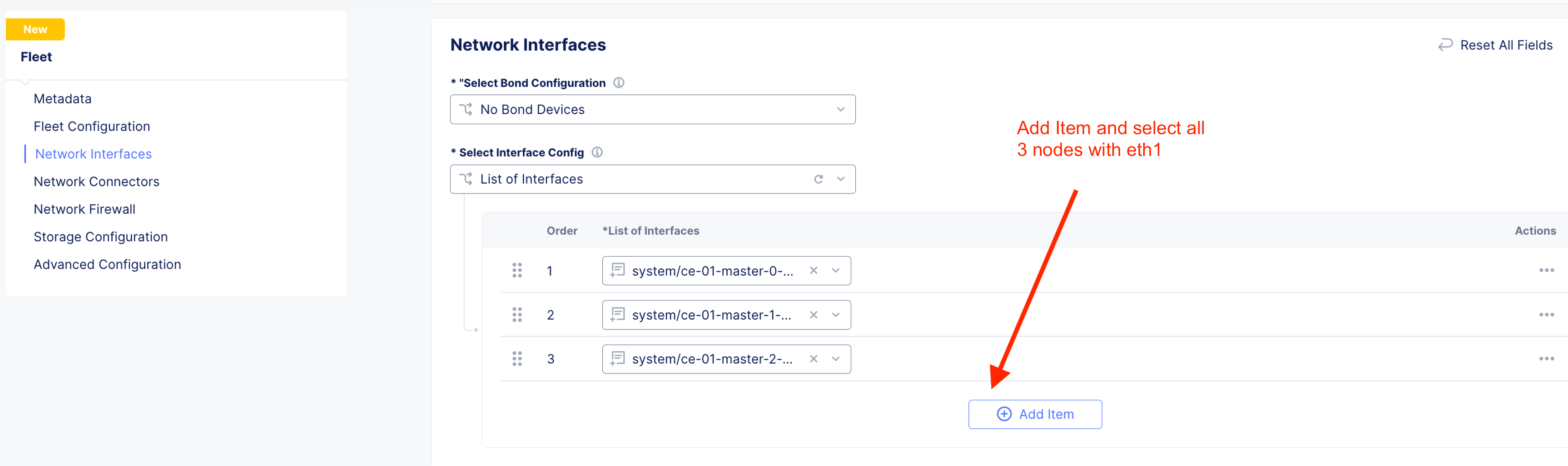
For this lab, create fleet and assinged those created interface to fleet.
Provide Fleet name and fleet label

Add all three or one (single node) to the fleet.
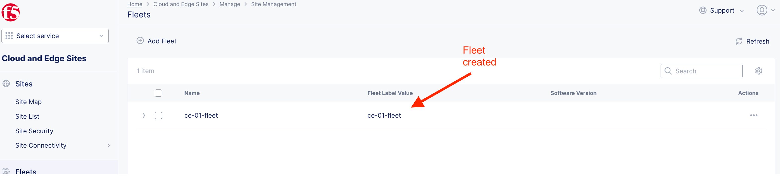
Fleet created
4.3 Attach fleet to CE
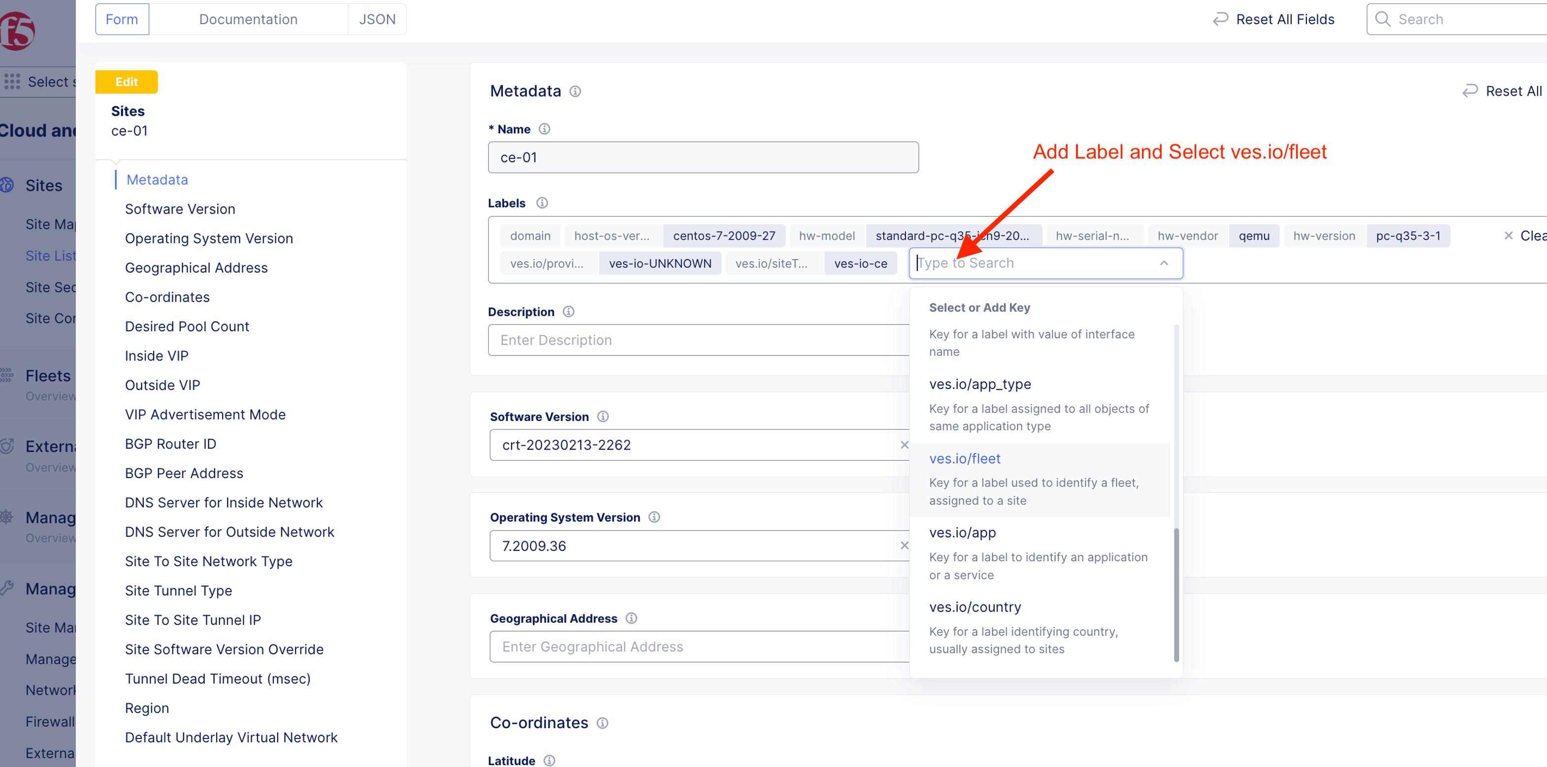
Attach fleet to CE by adding fleet label to the CE site
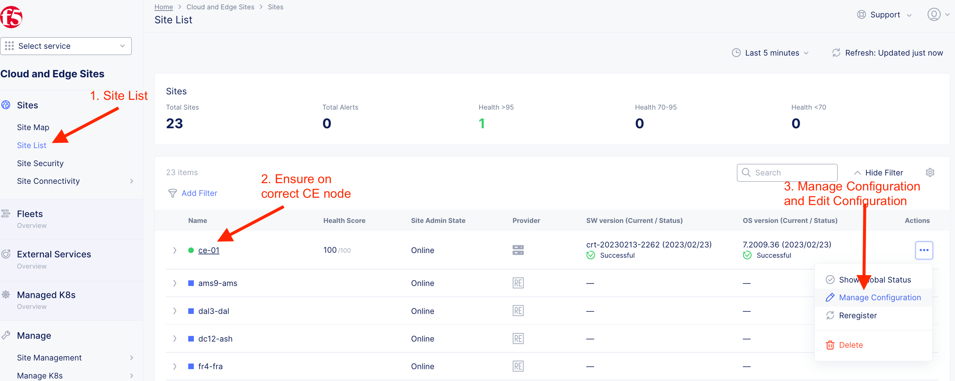
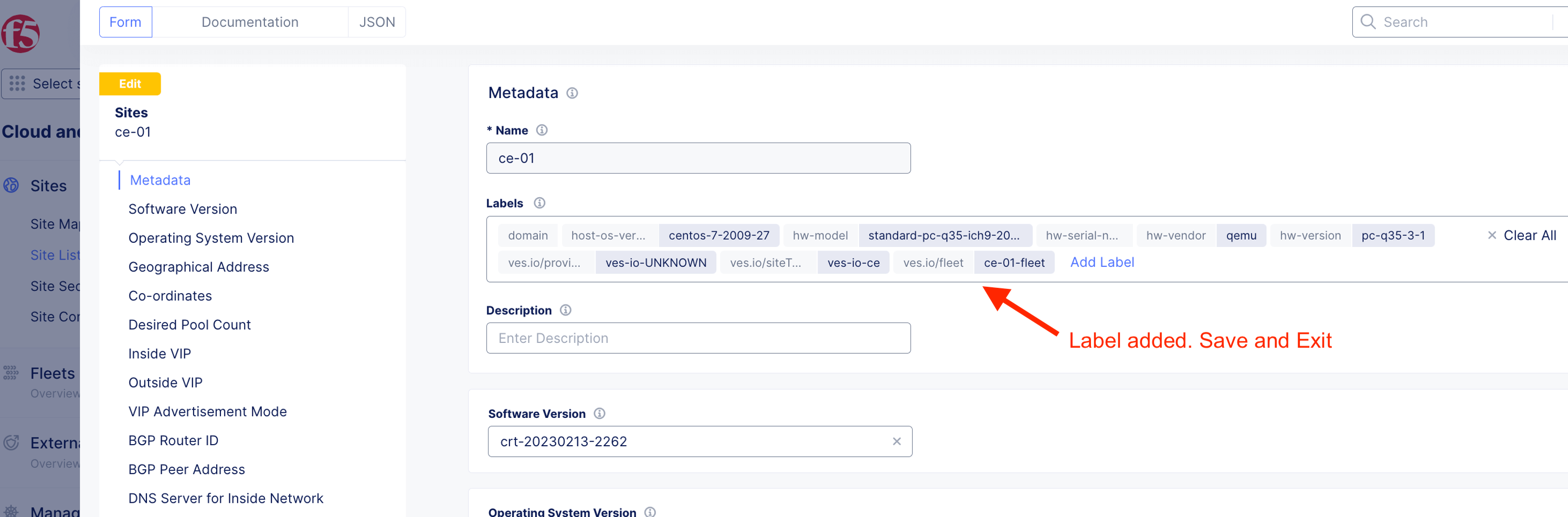
Add label and select ves.io/fleet as the key
Label added. Save and Exit.
4.4 Validate fleet working
master-0
Ensure correct eth1 IP shown on master-0

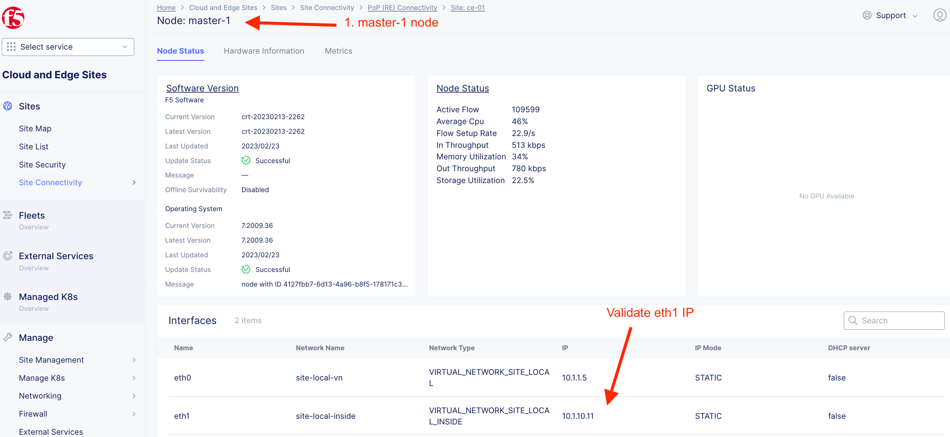
master-1
Ensure correct eth1 IP shown on master-1
master-2
Ensure correct eth1 IP shown on master-2

Advance BGP Setup (Optional)
By default, CE uses Virtual Router Redundancy Protocol (VRRP) to provides High availability for services advertised on CE. F5XC CE support BGP peering with neighbor router to spray traffic to CE via ECMP (Equal Cost Multi Path) Protocol.
Create BGP Peering
Create eth0 interface for respective CE nodes. This eth0 will be use for BGP peering with external router.
For simplicity, Copy and paste the following to create network interface.
ce-01-master-0-eth0
{
  "metadata": {
    "name": "ce-01-master-0-eth0",
    "namespace": "system",
    "labels": {},
    "annotations": {},
    "disable": false
  },
  "spec": {
    "type": "NETWORK_INTERFACE_ETHERNET",
    "mtu": 0,
    "dhcp_address": "NETWORK_INTERFACE_DHCP_DISABLE",
    "static_addresses": [
      {
        "prefix": "10.1.1.4",
        "plen": 24
      }
    ],
    "default_gateway": {
      "default_gateway_mode": "NETWORK_INTERFACE_GATEWAY_USE_CONFIGURED",
      "default_gateway_address": {
        "addr": "10.1.1.1"
      }
    },
    "DNS_server": {
      "dns_mode": "NETWORK_INTERFACE_DNS_USE_CONFIGURED",
      "dns_server": [
        {
          "addr": "10.1.1.1"
        }
      ]
    },
    "DHCP_server": "NETWORK_INTERFACE_DHCP_SERVER_DISABLE",
    "vlan_tagging": "NETWORK_INTERFACE_VLAN_TAGGING_DISABLE",
    "device_name": "master-0/eth0",
    "vlan_tag": 0,
    "priority": 0,
    "interface_ip_map": {},
    "is_primary": false,
    "monitor_disabled": {},
    "ethernet_interface": {
      "device": "eth0",
      "node": "master-0",
      "untagged": {},
      "static_ip": {
        "node_static_ip": {
          "ip_address": "10.1.1.4/24",
          "default_gw": "10.1.1.1",
          "dns_server": "10.1.1.1"
        }
      },
      "no_ipv6_address": {},
      "site_local_network": {},
      "mtu": 0,
      "priority": 0,
      "not_primary": {},
      "monitor_disabled": {}
    }
  }
}
ce-01-master-1-eth0
{
  "metadata": {
    "name": "ce-01-master-1-eth0",
    "namespace": "system",
    "labels": {},
    "annotations": {},
    "disable": false
  },
  "spec": {
    "type": "NETWORK_INTERFACE_ETHERNET",
    "mtu": 0,
    "dhcp_address": "NETWORK_INTERFACE_DHCP_DISABLE",
    "static_addresses": [
      {
        "prefix": "10.1.1.5",
        "plen": 24
      }
    ],
    "default_gateway": {
      "default_gateway_mode": "NETWORK_INTERFACE_GATEWAY_USE_CONFIGURED",
      "default_gateway_address": {
        "addr": "10.1.1.1"
      }
    },
    "DNS_server": {
      "dns_mode": "NETWORK_INTERFACE_DNS_USE_CONFIGURED",
      "dns_server": [
        {
          "addr": "10.1.1.1"
        }
      ]
    },
    "DHCP_server": "NETWORK_INTERFACE_DHCP_SERVER_DISABLE",
    "vlan_tagging": "NETWORK_INTERFACE_VLAN_TAGGING_DISABLE",
    "device_name": "master-1/eth0",
    "vlan_tag": 0,
    "priority": 0,
    "interface_ip_map": {},
    "is_primary": false,
    "monitor_disabled": {},
    "ethernet_interface": {
      "device": "eth0",
      "node": "master-1",
      "untagged": {},
      "static_ip": {
        "node_static_ip": {
          "ip_address": "10.1.1.5/24",
          "default_gw": "10.1.1.1",
          "dns_server": "10.1.1.1"
        }
      },
      "no_ipv6_address": {},
      "site_local_network": {},
      "mtu": 0,
      "priority": 0,
      "not_primary": {},
      "monitor_disabled": {}
    }
  }
}
ce-01-master-2-eth0
{
  "metadata": {
    "name": "ce-01-master-2-eth0",
    "namespace": "system",
    "labels": {},
    "annotations": {},
    "disable": false
  },
  "spec": {
    "type": "NETWORK_INTERFACE_ETHERNET",
    "mtu": 0,
    "dhcp_address": "NETWORK_INTERFACE_DHCP_DISABLE",
    "static_addresses": [
      {
        "prefix": "10.1.1.6",
        "plen": 24
      }
    ],
    "default_gateway": {
      "default_gateway_mode": "NETWORK_INTERFACE_GATEWAY_USE_CONFIGURED",
      "default_gateway_address": {
        "addr": "10.1.1.1"
      }
    },
    "DNS_server": {
      "dns_mode": "NETWORK_INTERFACE_DNS_USE_CONFIGURED",
      "dns_server": [
        {
          "addr": "10.1.1.1"
        }
      ]
    },
    "DHCP_server": "NETWORK_INTERFACE_DHCP_SERVER_DISABLE",
    "vlan_tagging": "NETWORK_INTERFACE_VLAN_TAGGING_DISABLE",
    "device_name": "master-2/eth0",
    "vlan_tag": 0,
    "priority": 0,
    "interface_ip_map": {},
    "is_primary": false,
    "monitor_disabled": {},
    "ethernet_interface": {
      "device": "eth0",
      "node": "master-2",
      "untagged": {},
      "static_ip": {
        "node_static_ip": {
          "ip_address": "10.1.1.6/24",
          "default_gw": "10.1.1.1",
          "dns_server": "10.1.1.1"
        }
      },
      "no_ipv6_address": {},
      "site_local_network": {},
      "mtu": 0,
      "priority": 0,
      "not_primary": {},
      "monitor_disabled": {}
    }
  }
}
All interfaces created for eth0 (SLO)
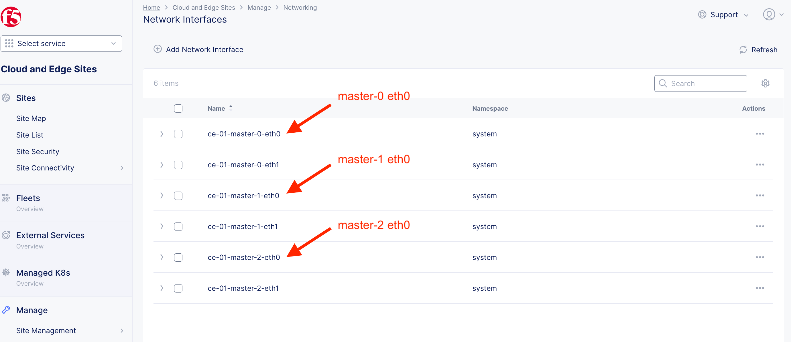
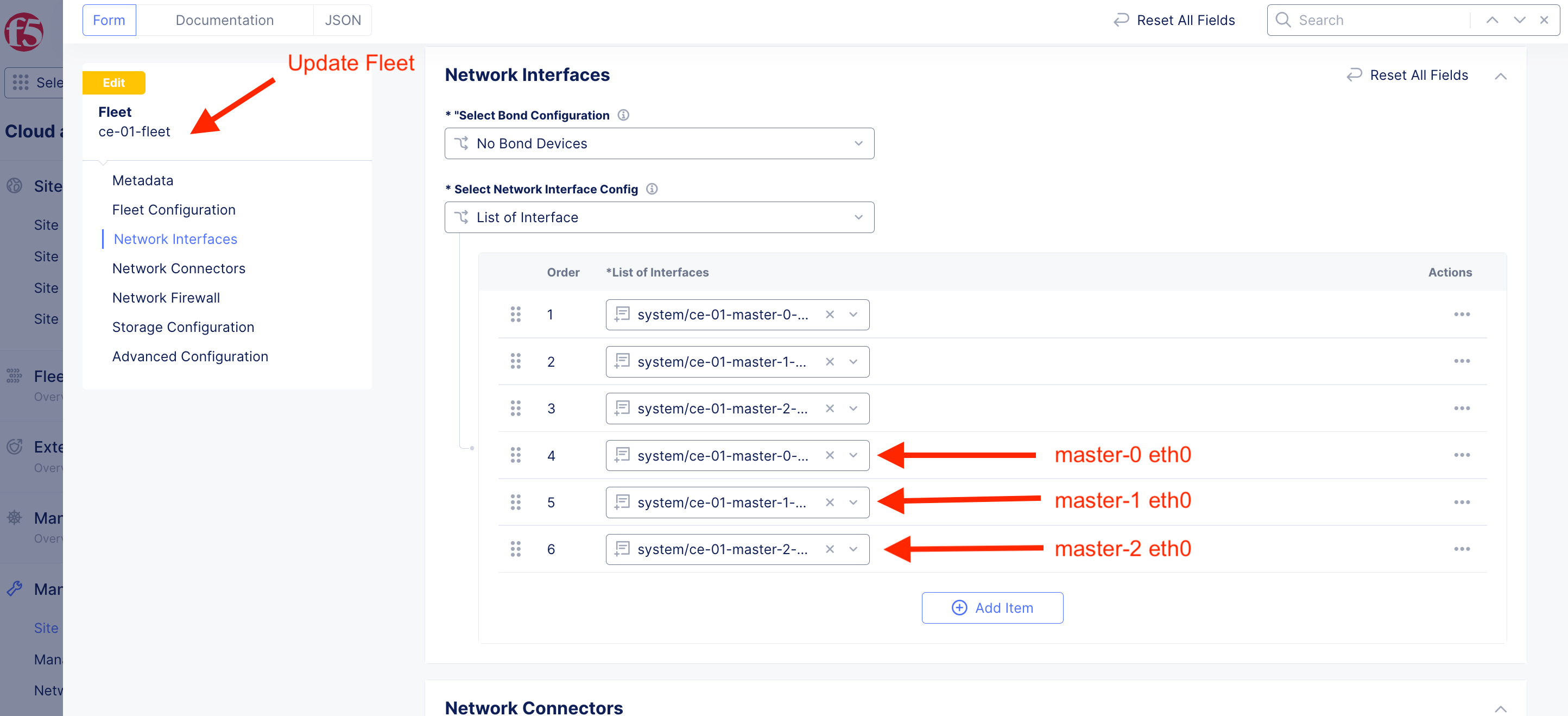
Update existing fleet to add eth0 for all nodes
Create F5XC BGP Settings

Instead of manually creating, you can have the options to copy and paste config below.
Please ensure you change the BGP name to reflect your CE
ce-01-bgp-to-ext-frr
{
  "metadata": {
    "name": "ce-01-bgp-to-ext-frr",
    "namespace": "system",
    "labels": {},
    "annotations": {},
    "disable": false
  },
  "spec": {
    "where": {
      "site": {
        "ref": [
          {
            "kind": "site",
            "namespace": "system",
            "name": "ce-01"
          }
        ],
        "network_type": "VIRTUAL_NETWORK_SITE_LOCAL",
        "disable_internet_vip": {}
      }
    },
    "bgp_parameters": {
      "asn": 64512,
      "local_address": {},
      "bgp_router_id_type": "BGP_ROUTER_ID_FROM_INTERFACE"
    },
    "peers": [
      {
        "metadata": {
          "name": "ce-01-master-0-to-ext-frr-peer",
          "disable": false
        },
        "external": {
          "asn": 64512,
          "address": "10.1.1.9",
          "port": 179,
          "interface": {
            "namespace": "system",
            "name": "ce-01-master-0-eth0",
            "kind": "network_interface"
          }
        },
        "passive_mode_disabled": {},
        "target_service": "frr"
      },
      {
        "metadata": {
          "name": "ce-01-master-1-to-ext-frr-peer",
          "disable": false
        },
        "external": {
          "asn": 64512,
          "address": "10.1.1.9",
          "port": 179,
          "interface": {
            "namespace": "system",
            "name": "ce-01-master-1-eth0",
            "kind": "network_interface"
          }
        },
        "passive_mode_disabled": {},
        "target_service": "frr"
      },
      {
        "metadata": {
          "name": "ce-01-master-2-to-ext-frr-peer",
          "disable": false
        },
        "external": {
          "asn": 64512,
          "address": "10.1.1.9",
          "port": 179,
          "interface": {
            "namespace": "system",
            "name": "ce-01-master-2-eth0",
            "kind": "network_interface"
          }
        },
        "passive_mode_disabled": {},
        "target_service": "frr"
      }
    ]
  }
}
Login to ext_router
Configure external router to do iBGP with CE nodes.
ext-router
ubuntu@ext-router:~$ vtysh
% Can't open configuration file /etc/frr/vtysh.conf due to 'Permission denied'.

Hello, this is FRRouting (version 7.2.1).
Copyright 1996-2005 Kunihiro Ishiguro, et al.

ext-router#
Execute the following command
ext-router# configure terminal
ext-router(config)# router bgp 64512
ext-router(config-router)# neighbor 10.1.1.4 remote-as 64512
ext-router(config-router)# neighbor 10.1.1.5 remote-as 64512
ext-router(config-router)# neighbor 10.1.1.6 remote-as 64512
ext-router(config-router)# end
ext-router# wr
Note: this version of vtysh never writes vtysh.conf
Building Configuration...
Integrated configuration saved to /etc/frr/frr.conf
[OK]
Show running configuration
ext-router# show running-config
Building configuration...

Current configuration:
!
frr version 7.2.1
frr defaults traditional
hostname ext-router
log syslog informational
no ipv6 forwarding
service integrated-vtysh-config
!
router bgp 64512
 neighbor 10.1.1.4 remote-as 64512
 neighbor 10.1.1.5 remote-as 64512
 neighbor 10.1.1.6 remote-as 64512
!
line vty
!
end
show ip bgp summary
ext-router# show ip bgp summary

IPv4 Unicast Summary:
BGP router identifier 10.1.20.21, local AS number 64512 vrf-id 0
BGP table version 1
RIB entries 1, using 184 bytes of memory
Peers 3, using 61 KiB of memory

Neighbor        V         AS MsgRcvd MsgSent   TblVer  InQ OutQ  Up/Down State/PfxRcd
10.1.1.4        4      64512      15      14        0    0    0 00:00:59            1
10.1.1.5        4      64512      15      14        0    0    0 00:00:59            1
10.1.1.6        4      64512      15      14        0    0    0 00:00:57            1

Total number of neighbors 3
show ip route
ext-router# show ip route
Codes: K - kernel route, C - connected, S - static, R - RIP,
       O - OSPF, I - IS-IS, B - BGP, E - EIGRP, N - NHRP,
       T - Table, v - VNC, V - VNC-Direct, A - Babel, D - SHARP,
       F - PBR, f - OpenFabric,
       > - selected route, * - FIB route, q - queued route, r - rejected route

K>* 0.0.0.0/0 [0/100] via 10.1.1.1, ens5, src 10.1.1.9, 00:12:21
C>* 10.1.1.0/24 is directly connected, ens5, 00:12:21
K>* 10.1.1.1/32 [0/100] is directly connected, ens5, 00:12:21
B>* 10.1.1.100/32 [200/255] via 10.1.1.4, ens5, 00:01:25
  *                         via 10.1.1.5, ens5, 00:01:25
  *                         via 10.1.1.6, ens5, 00:01:25
C>* 10.1.20.0/24 is directly connected, ens6, 07:38:43
Note
BGP route will only shown when a HTTP/TCP LB configured to advertise custom. As shown above, 10.1.1.100 is the advertised VIP. When traffic hit the external router, external router will send to CE node respectively.
- master-0 [10.1.1.4]
- master-1 [10.1.1.5]
- master-2 [10.1.1.6]